-
Notifications
You must be signed in to change notification settings - Fork 65
GridTool
Prev (Reference tool) | Home | Manual | Index | (Color palette tool) Next
Table of contents
The grid tool is an add-on to the reference tool. It is used to reference maps with a grid for which the coordinate system is known.
While in the reference tool manual input of coordinates is required for each reference point, the grid tool needs only a description of the coordinate system used in the map and the coordinates of just one reference point. 3 other reference points in the grid must be defined by clicking on them in the map.
The grid tool automatically creates additional reference points on the grid in a user-defined area. If necessary, the reference tool can help to improve the positions of reference points created with the grid tool.
To work with the QMT grid tool proceed as follows (compare the images in the example section):
- Select the menu entry
Window - Shellto open a shell window (docked window, can be moved on the desktop). - Click the
Reference toolbutton in the QMTToolswindow (docked window, can be moved on the desktop). - Click the
Open(Add map files to list) icon ( ) and select a raster map with a grid and known coordinate system for the grid (this means: some
form of the Proj.4 description of the coordinate system should be known).
The raster map is loaded into the QMT map window.
 - Click the grid tool icon (
 ) in the reference tool to open the grid tool (docked window, can be moved on the desktop).
 - Zoom the map with the mouse wheel so that 1 complete grid square is displayed in the window (make it as large as reasonable).
- Click the coordinate system selection icon (
 )
) - Choose the coordinate system of the grid (coordinate systems may have degree or meter as unit). If the coordinate system is not in the list provided by QMT, then check if it can be found in the list of some additional coordinate systems or in one of the links given there.
- Get the coordinates of the upper left corner of a grid square (coordinates must match the coordinate system defined in the previous step!).
- Insert easting/longitude and northing/latitude into their fields. Use meters with easting/northing and degrees with longitude/latitude.
- Define the horizontal and vertical size (spacing) of the considered grid square with the unit used in the previous point.
- Select the next (second) radio button.
- Go to the map and left-click the upper left corner of the grid square. This selects the first reference point (remember: the coordinates of this point have been defined earlier).
- Select each of the 3 neighbors in the square in the tool window and click the corresponding grid corners of the map. This defines 3 additional reference points. The coordinates of these points are calculated from the grid size defined earlier. All reference points up to this step are displayed on the map as small orange squares.
- Click the
Set areabutton in the grid tool. A black-framed rectangle appears in the map window (zoom out if not visible!). Within this area the tool creates additional grid points (shown as small black points). - To change the size of the area click in the square at the upper left or lower right corner of the area frame to fix the mouse to this corner, move the mouse to the wanted new location and left-click again to fix the corner.
- Click
Okto close the grid tool. - In the reference tool there appears now a list of reference points. If necessary, the positions of the reference points can be improved as described in the reference tool section.
- Proceed with the reference tool as described there.
-
Feel free to use the 4 vertices of an arbitrary grid rectangle. If doing so, the horizontal resp. vertical spacing values should be the length of the horizontal resp. vertical edges of the rectangle. This approach can reduce the number of reference points created automatically by the grid tool.
-
Selecting the second radio button in the tool window and clicking
Resetin the big gray square deletes all reference points (but not the coordinate system definition). -
Clicking the
Resetbutton at the button of the tool window deletes the coordinate system definition and the selected reference points. -
Clicking the
Cancelbutton closes the grid tool without transferring the referenced points to the reference tool. -
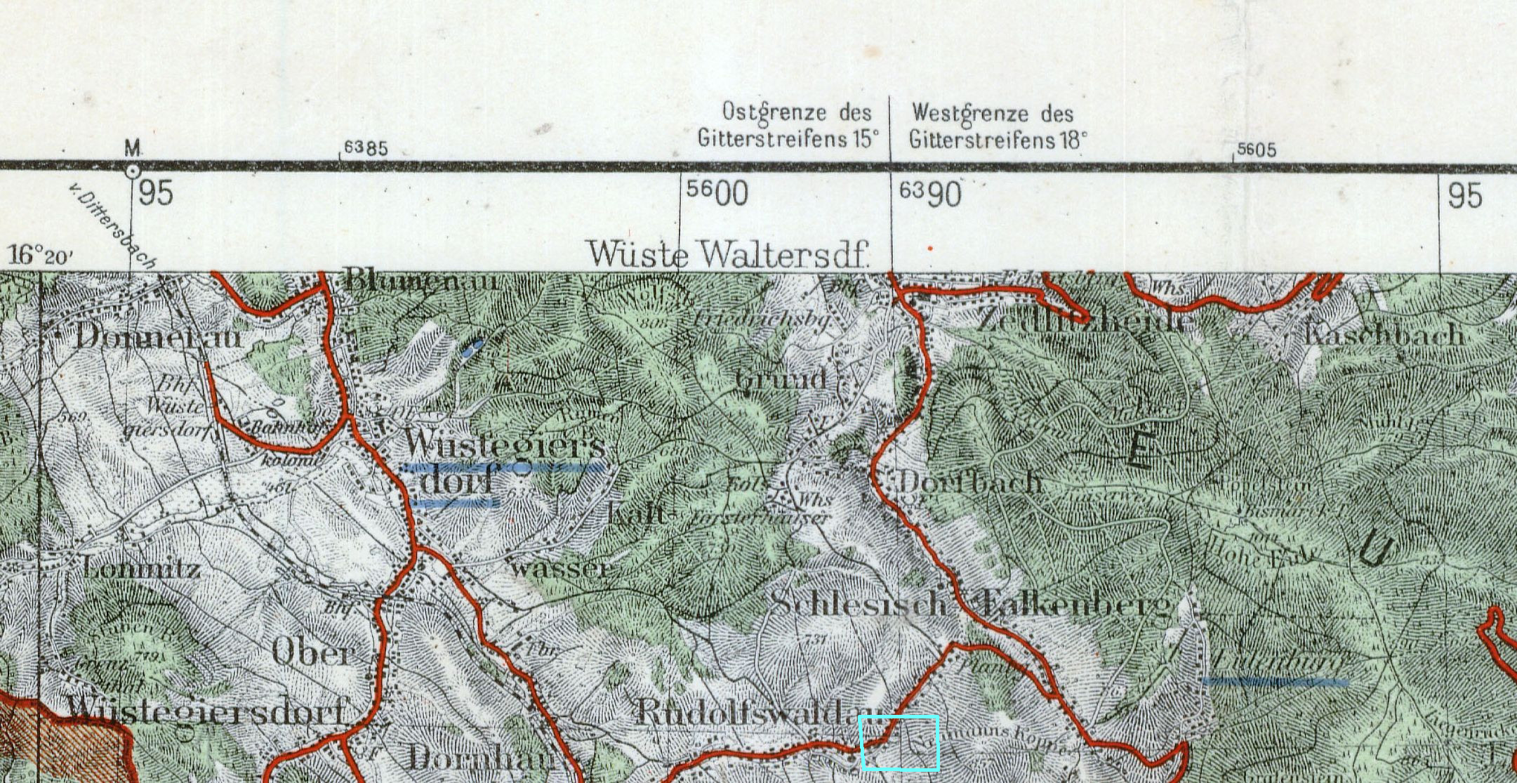
The grid tool can be used repeatedly when referencing a map and even with different coordinate systems. After finishing one run of the grid tool re-open it from the reference tool. If necessary, define a new coordinate system in the grid tool. New reference points created in the next grid tool run are appended to the list already existing reference points. This can be useful if there are different grid coordinate systems used in one raster map (e.g. grids for 2 different Gauß-Krüger zones covered by the map). The following image illustrates such a situation where the left part of the map belongs to the Gauß-Krüger zone 5, the right one to the zone 6 (look at labels Ostgrenze, Westgrenze marking the zone boundary). Pay attention to the fact that in this case grid lines are broken (see cyan rectangle for northing and jump in the easting value)!
-
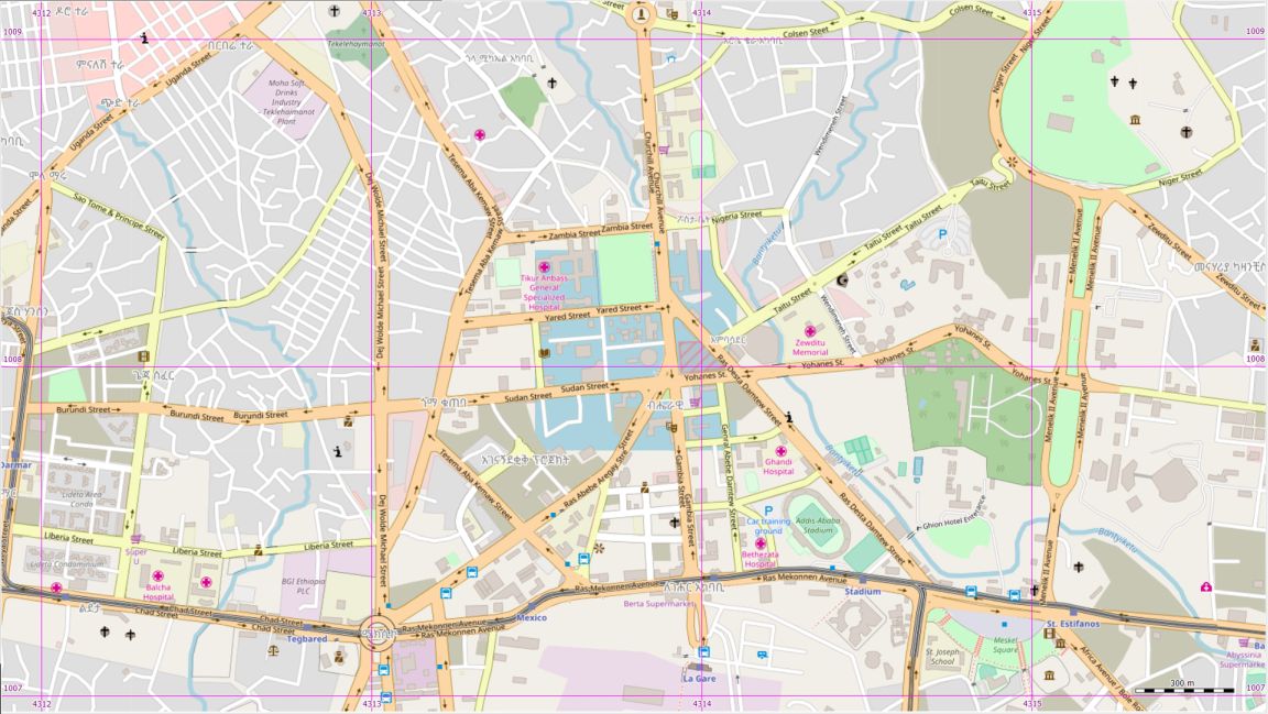
Used map: OpenStreetMap displayed in QMS, screen snapshot of center of Addis Abeba, Ethiopia
-
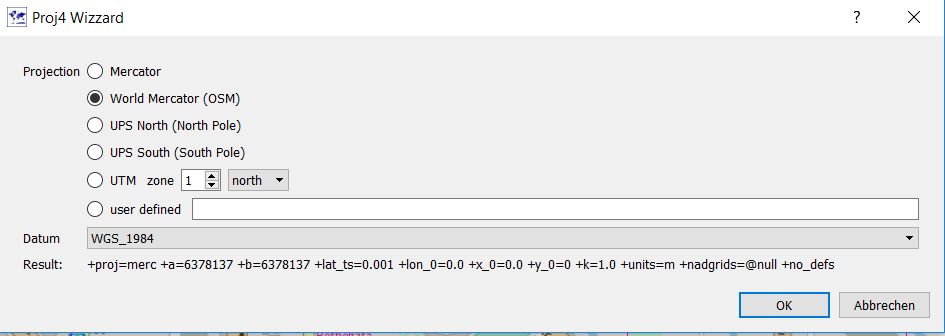
Grid used: EPSG 3857, WGS 84 / Pseudo-Mercator (selected in QMS/QMT via "World Mercator (OSM) - datum WGS_1984"):

-
Proj.4 parameters:
+proj=merc +a=6378137 +b=6378137 +lat_ts=0.001 +lon_0=0.0 +x_0=0.0 +y_0=0 +k=1.0 +units=m +nadgrids=@null +no_defs -
Open grid tool for referencing
-
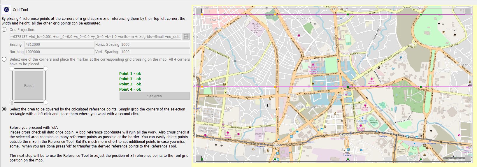
Upper left grid corner used as first grid point and then then 3 immediate neighbors (orange points in upper left corner)
-
Coordinates of first point: Easting: 4312000 (m), Northing: 1009000 (m), horiz./vert. spacing: 1000 (m) (grid unit is km, square size is 1km by 1 km)
-
number of reference points added by QMT: 8 (small green squares, returning back to the reference tool all reference points are shown as small black squares)
-
no additional refinement of automatically created reference points in the reference tool (precision of obtained reference points seems to be sufficient)
-
Result when displaying referenced map in QMS: differences in grid lines and streets between original OSM map and referenced map practically not visible (inside the black frame is the referenced map, outside the original one).

-
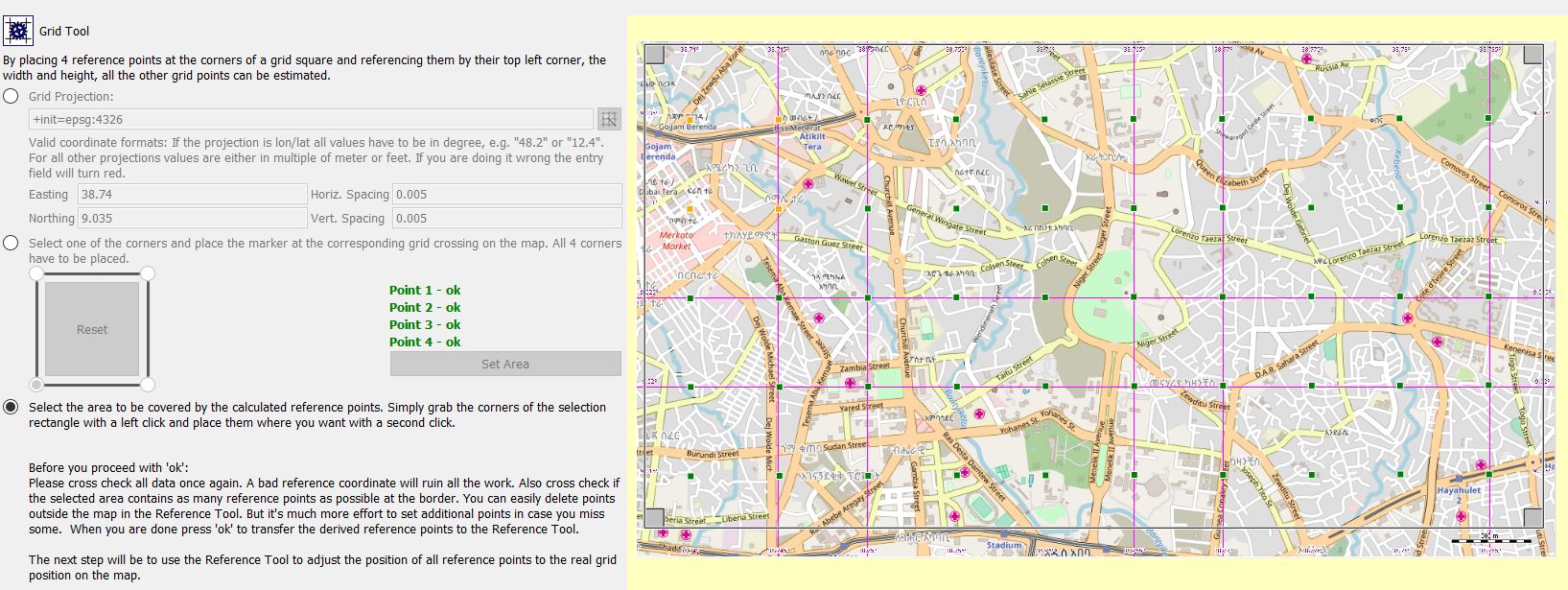
Similar to Example 1
-
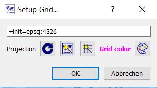
Grid used: EPSG 4326 (WGS84 geographic)
-
Proj.4 parameters:
+init=epsg:4326 -
Coordinates of first point N9.035°, E38.74 (easting: longitude, northing: latitude, spacing in degrees)
-
no additional refinement of automatically created reference points
Prev (Reference tool) | Home | Manual | Index | Top | (Color palette tool) Next