-
Notifications
You must be signed in to change notification settings - Fork 190
SBUS Protocol
The SBUS Protocol is a serial protocol that was developed by Futaba for hobby remote control applications. It is derived from the RS232 protocol but the voltage levels are inverted. The protocol provides 16 channels of 11 bits each, two digital channels, and two flags for "frame lost" and "failsafe".
- 100'000 Baud rate (this is a non standard baud rate!)
- 8E2 configuration, i.e.:
- 1 start bit
- 8 Data bits
- 1 Even parity bit
- 2 Stop bits
Note: The voltage levels of SBUS are inverted. So while a 0 with a normal serial port is encoded with a low voltage, it is encoded with a high voltage with SBUS.
Note: Even parity means that, for a given set of bits, the occurrences of bits whose value is 1 is counted. If that count is odd, the parity bit value is set to 1, making the total count of occurrences of 1s in the whole set (including the parity bit) an even number. If the count of 1s in a given set of bits is already even, the parity bit's value is 0.
A single SBUS message is 25 bytes long an therefore, with the configuration described above, takes 3ms to be transmitted. It consists of the following bytes:
- 1 Header byte 00001111b (0x0F)
- 16 * 11 bit channels -> 22 bytes
- 1 Byte with two digital channels (channel 17 and 18) and "frame lost" and "failsafe" flags
- 1 Footer byte 00000000b (0x00)
Each byte is composed of 8 bits with IDs as follows [7 6 5 4 3 2 1 0] where bit 0 is the least significant bit. The data of the 16 channels are distributed onto the 22 data bytes starting with the least significant bit of channel 1 as follows (using the notation CHANNEL.BIT_ID):
- data byte 0: [1.7 1.6 1.5 1.4 1.3 1.2 1.1 1.0]
- data byte 1: [2.4 2.3 2.2 2.1 2.0 1.10 1.9 1.8]
- data byte 2: [3.1 3.0 2.10 2.9 2.8 2.7 2.6 2.5]
- data byte 3: ...
The digital channels and flag bytes is composed as:
- flag byte: [0 0 0 0 failsafe frame_lost ch18 ch17]
Since the least significant bit is sent first over the serial port, the following bit sequence is transmitted:
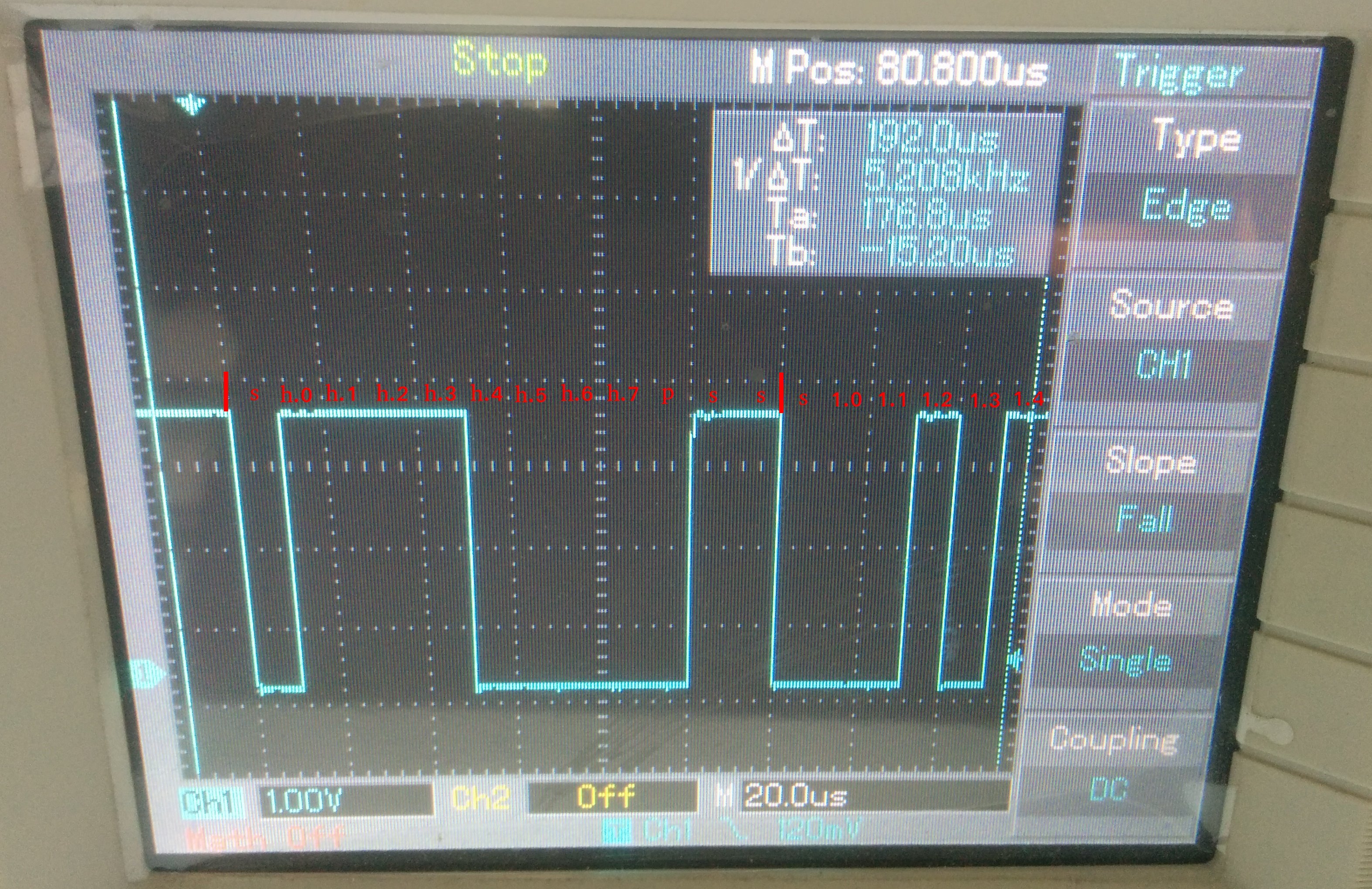
shhhhhhhhpss | s 1.0 1.1 1.2 1.3 1.4 1.5 1.6 1.7 pss | s 1.8 1.9 1.10 2.1 2.2 2.3 2.4 pss | ...
The following image shows the beginning of an inverted SBUS message (i.e. normal serial) on the oscilloscope:

- Each of the 16 channels use values in the range of 192 - 1792 which are mapped linearly in the Betaflight Firmware to values in the range 1000 - 2000. These values in the range [1000, 2000] are also what can be observed in the Betaflight Configurator's Receiver tab. Note that e.g. a Taranis transmitter sends values in a slightly larger range than [192, 1792] but these values will later be cropped.