Multi-platform Pascal cross-compiler for Microchip 8 bits PIC microcontrollers.
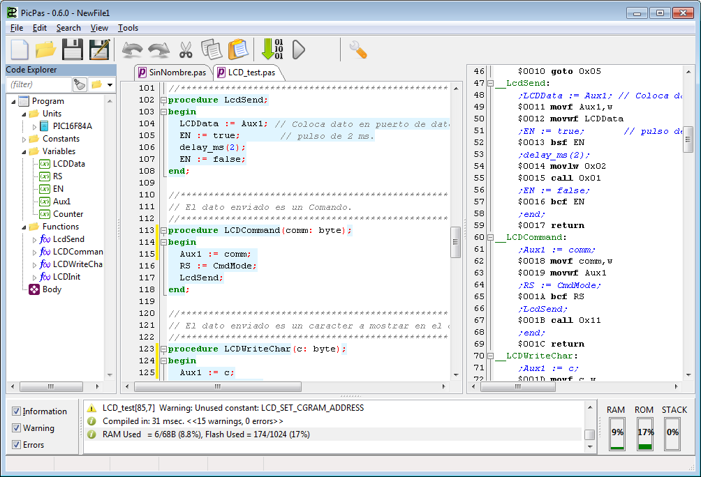
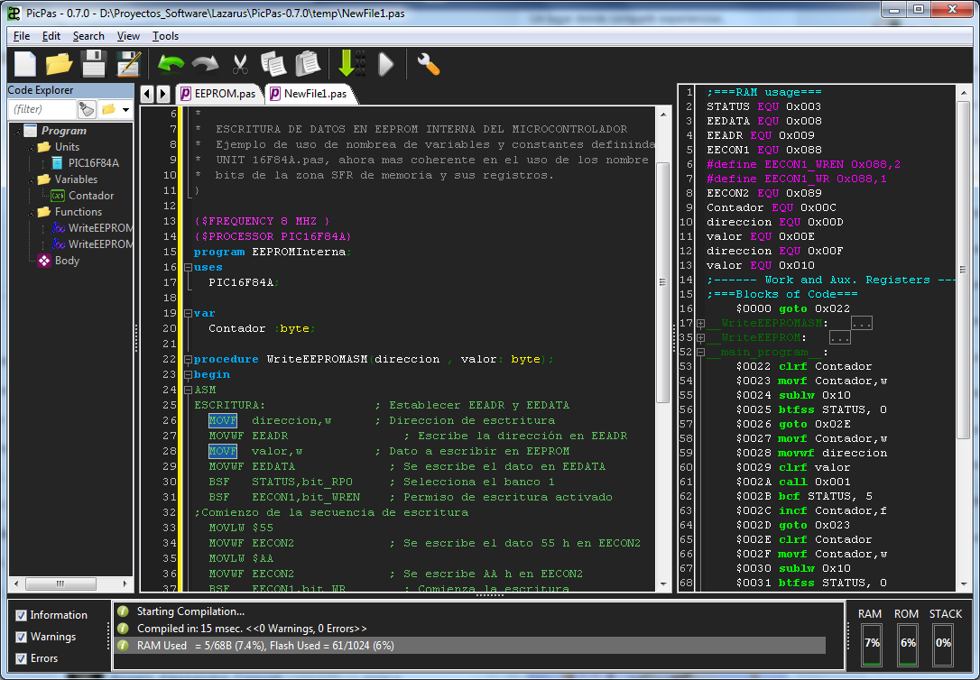
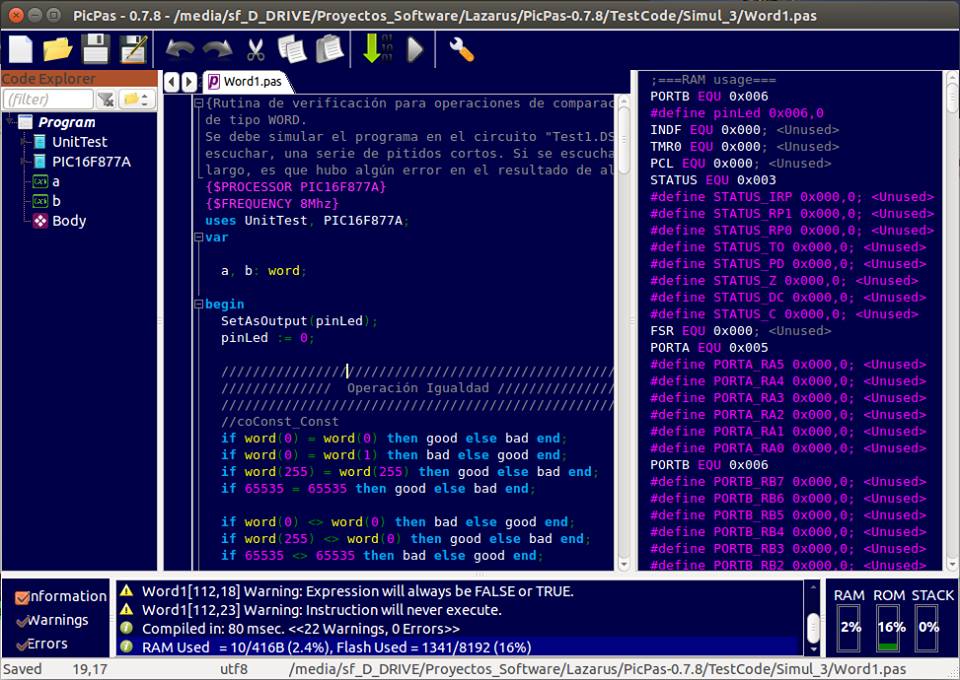
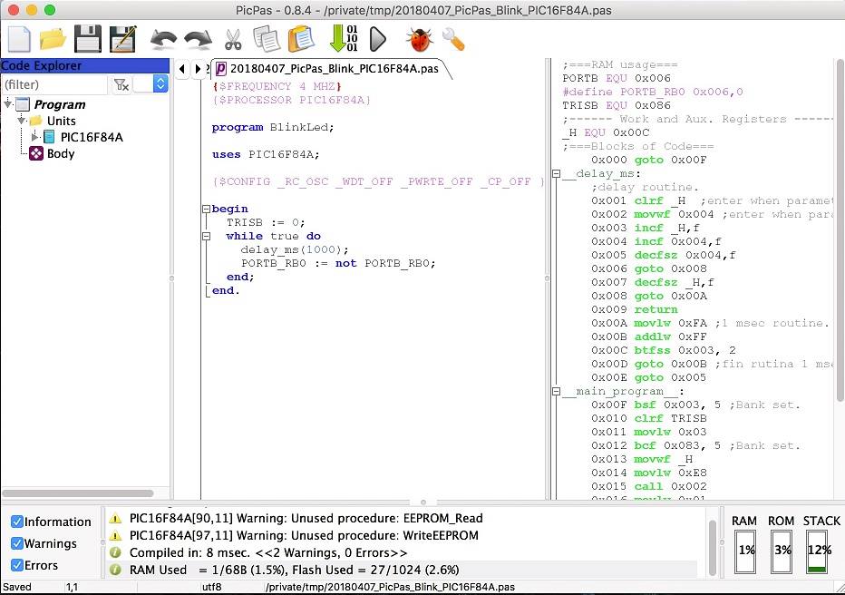
PicPas is a Pascal compiler and IDE, written in Lazarus, which generates executable code for Baseline and Mid-range PIC microcontrollers.
No additional libraries or software required to compile. PicPas generates the *.hex file directly.
PicPas works with a simplified version of the Pascal language, that has been adapted to work with limited resources small devices.
Currently, it only supports basic types.
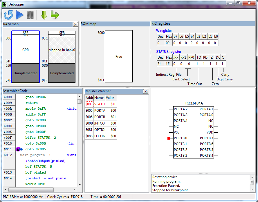
It includes a complete IDE/debugger/simulator to facilitate the development.
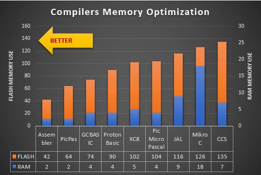
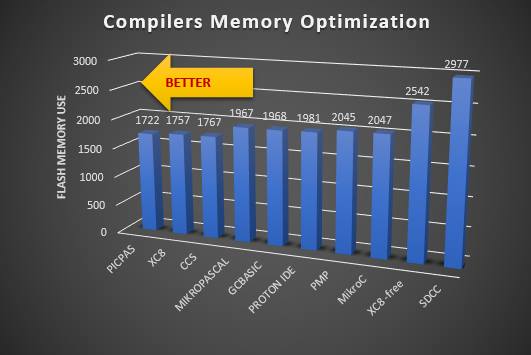
The PicpPas compiler includes advanced optimization options so the code obtained is generally more compact than the obtained with other compilers.
PicPas doesn't need installation, and have not dependencies, except the commons of the operative system, where it's runnig.
To run, it's only needed to download the folder from GitHub. There is compiled binaries for Windows-64 version (PicPas-win64.exe), Ubuntu version (PicPas-linux) and a Mac version (PicPas-Mac.dmg).
If it's required other platform, it need to be compiled from the source code.
When starting, PicPas could generate warning messsages, if not needed folders exist.
As an example the following code, is to blink a LED on port B:
{Sample program to blink a Led on PORTB.7}
program BlinkLed;
uses PIC16F84A;
{$FREQUENCY 8MHZ}
var
  pin: bit absolute PORTB.7;
begin
  TRISB := 0;   //all outputs
  while true do
    delay_ms(1000);
    pin := not pin;
  end;
end.
The processor target is defined including the correspondent unit in the USES section.
The CPU clock is defined using the directive {$FREQUENCY } and must be after the USES section.
Almost all the Mid-range and Baseline PIC devices are supported:
PIC10F200 PIC10F200 PIC10F202 PIC10F204 PIC10F206 PIC10F220 PIC10F222
PIC12F508 PIC12F509 PIC12F510 PIC12F519
PIC16F505 PIC16F506 PIC16F526 PIC16F527 PIC16F54 PIC16F57 PIC16F59
PIC10F320 PIC10F322
PIC12F609 PIC12F615 PIC12F617 PIC12F629 PIC12F635 PIC12F675 PIC12F683 PIC12F752
PIC16F73 PIC16F74 PIC16F76 PIC16F77 PIC16F83 PIC16F84 PIC16F87 PIC16F88
PIC16F610 PIC16F616 PIC16F627 PIC16F627A PIC16F628 PIC16F628A PIC16F630 PIC16F631 PIC16F636 PIC16F639 PIC16F648A PIC16F676 PIC16F677 PIC16F684 PIC16F685 PIC16F687 PIC16F688 PIC16F689 PIC16F690
PIC16F707 PIC16F716 PIC16F720 PIC16F721 PIC16F722 PIC16F722A PIC16F723 PIC16F723A PIC16F724 PIC16F726 PIC16F727 PIC16F737 PIC16F747 PIC16F753 PIC16F767 PIC16F777 PIC16F785
PIC16F818 PIC16F819 PIC16F870 PIC16F871 PIC16F872 PIC16F873 PIC16F874 PIC16F874A PIC16F876 PIC16F877 PIC16F882 PIC16F883 PIC16F884 PIC16F886 PIC16F887
PIC16F913 PIC16F914 PIC16F916 PIC16F917 PIC16F946
Support are implemented using units. So if we need compile to the PIC16f628A, we write:
program anything;
uses PIC16F628A;
begin
  ...
end.
There is not yet support for Enhanced Mid-range, or the PIC18 High-preformance families of PIC.
PicPas includes an IDE integrated to the compiler, to help on developing the programs.
Some features of the IDE are:
• Cross-platform.
• Multiple editors windows.
• Syntax highlighting, code folding, word, and line highlighting for Pascal and ASM.
• Code completion, and templates for the common structures IF, REPEAT, WHILE, …
• Shows the assembler code and the resources used.
• Support for themes (skins).
• Code tools for completion and navigation.
• Check syntax in REAL TIME!!!.
• Several setting options.
• Translated to english, french, spanish and german.
PicPas includes a graphical debugger/simulator for instructions of the Mid-Range core:
To control the execution, the following keys can be used:
F5 -> Set a breakpoint in the current position of the assembler code. F6 -> Reste the device. F7 -> Step by step into subroutine. F8 -> Step by step over subroutine. F9 -> Run the program in real time.
PisPas has been compared in two code optimization competition against the best profesional compilers for PIC microcontrollers, obtaining the first place in both.
Firts competition
Compiling a simple light sequence: https://github.com/AguHDz/PicPas-Librerias_y_Programas/tree/master/Comparacion%20PicPas-Otros%20Compiladores
Result:
Second competition
Compiling a digital clock using I2C and the DS1307: https://www.facebook.com/groups/electronicaymicrocontroladores/permalink/1812269192135162/
Result
program <Name>;  //optional
uses
  //Units declarations

const
  //Constants declarations

var
  //Variables declarations

//<Procedures declaration>

begin
  //Main program body
end.
unit <name>;
interface
uses
  //units declaration
const
  //Constant declaration
var
  //Variable declaration

//Procedures declaration

implementation

uses
  //units declaration
const
  //Constant declaration
var
  //Variable declaration

//Procedures implementation

end.
Operator            Precedence
=================== ==========
 NOT, sign “-“         6
 *, DIV, MOD, AND      5
 +, -, OR, XOR         4
 =, <>, <, <=, >, >=   3
 := +=                 2
Type           Size
============== ==========
 bit           1 bit
 boolean       1 bit
 byte          1 byte
 char          1 byte
 word          2 bytes
 dword         4 bytes
Numerical types are all unsigned.
Variables are defined with the VAR keyword:
var
  var1 : byte;
  var2 : bit;
  large_name_variable: boolean;
Variables can be defined too, at an absolute memory address:
var
  PORTB: BYTE absolute $06;
  pin0: bit; absolute $06.0;
  pin1: boolean; absolute PORTB.bit1;
Bit access can be performed too, using fields:
  var_byte.bit0 := 1;
  var_byte.bit7 := 0;
Specific byte of a word, can be access using fields:
  word_var.Low := $ff;
  word_var.High := $ff;
PicPas doens't follow the common Pascal syntax. Instead, a new Modula-2, style syntax is implemented.
The common control structures have the following forms:
IF <condition> THEN
  <block of code>
END;

IF <condition> THEN
  <block of code>
ELSE
  <block of code>
END;

IF <condition> THEN
  <block of code>
ELSIF <condition> THEN
  <block of code>
ELSE
  <block of code>
END;

WHILE <condition> DO
  <block of code>
END;

REPEAT
  <block of code>
UNTIL <condition>;

FOR  <variable> := <start-value> TO <end-value> DO
  <block of code>
END;
System functions are always available in code. They don't need to be defined or included in a unit.
FUNCTION       DESCRIPTION
============== =================================================
delay_ms()	   Generate a time delay in miliseconds, from 0 to 65536.
Inc()          Increase a variable.
Dec()          Decrease a varaible.
SetBank()      Set the current RAM bank.
Exit()         Exit from a procedure or end the program.
Ord()          Convert a char to a byte.
Chr()          Convert a byte to a char.
Bit()          Convert an expression to a bit expression.
Byte()         Convert an expression to a byte expression.
Word()         Convert an expression to a word expression.
DWord()        Convert an expression to a dword expression.
SetAsInput()   Set a 8-bits port or a pin as an input.
SetAsOutput()  Set a 8-bits port or a pin as an output.
PicPas use the Modula-2 syntax for procedures and functions:
Proedures are declared in the common Pascal syntax:
  procedure proc2(par1: byte);
  begin
    if par1 = 0 then
      exit;
    else
      par1 := 5;
    end;
  end;
Functions are declared the same, but indicating the type to return:
procedure TheNext(par1: byte): byte;
begin
  exit(par1 + 1);
end;
The return value is indicated with the exit() instruction.
When using in procedures parameters, a REGISTER parameter can be included:
procedure QuickParameterProc(register regvar: byte);
begin
  //Be carefull if put some code here
  PORTB := regvar;
end;
REGISTER parameters are fast, because they use the W register, so only one REGISTER parameter can be used. As REGISTER parameter is stored in W register, any operation using the W register, could lose its value, so the first operation in a procedure, using a REGISTER parameter must be read this parameter.
To manage interrupts, PicPas let us to define a special kind of Procedure:
  procedure My_ISR; interrupt;
  begin

    //ISR code

  end;
The name of the procedure is not important, but the declaration must be followed but the reserved word INTERRUPT.
Only one INTERRUPT procedure is allowed in a program.
When PicPas compile an INTERRUPT procedure, some special criterias are considered:
- Are always compiled starting in the address 0x0004.
- A RETFIE instruction is added to the end of the routine.
- No additional bank switching instructions are generated at the beginning of the procedure. It is the responsibility of the programmer to properly handle the banks within the routine.
INTERRUPT procedures don't save the value of registers or the control flags. This should be done manually.
PicPas have a complete support for inserting ASM code inside the Pascal source.
ASM blocks must be included between the delimiters ASM and END:
procedure DoSomething;
begin
  x := 10;
  asm
    ;Add 2 to the address $20
    MOVLW 2
    ADDWF $20, F
  end
end;
ASM blocks are not instructions, that's why they are not finished with ";". It lets the ASM block, to be included in almost any place of the source code, like a comment.
WARNING: Changing the RAM bank, inside an ASM block, can generate errors in compilation or in the code compiled. PicPas know always the current RAM bank, when compiling, but is not aware of the changes can be made inside ASM blocks.
Absolute and relative Labels can be used too:
asm
  GOTO $+1   ;jump one position forward
end
asm
  ;infinite loop
label:
  NOP
  GOTO label
end
Program variables can be accessed, using his common name:
var
 byte1: byte;
 car1: char;
 bit1: bit;
 bol1: boolean;
 word1: word;
 dword1: dword;
begin
  //Low level clear
  asm
    CLRF byte1
    CLRF car1
    BCF bit1
    BCF bol1
    CLRF word1.Low
    BCF word1.high.bit1
	CLRF dword1.low
	CLRF dword1.high
	CLRF dword1.extra
	CLRF dword1.ultra
  end
end.
Constant can be accessed too, using the same way.
It's possible to use the directive ORG inside a ASM block, too:
  asm
    org $-2
  end
  vbit := 1;
The address in ORG, can be absolute or relative.
WARNING: Changing the PC pointer with ORG, can generate errors in the compilation or in the code compiled.
Pointers are supported in PicPas, only for addresses going from $00 to $FF (1 byte size), thus they can cover only the RAM memory in banks 0 and 1.
Pointers must be declared usin first, a type declaration in the common Pascal style:
type
  ptrByte: ^Byte;
  ptrByte: ^Word;
var
  pbyte: ptrByte;
  pword: ptrWord;
Pointers can be assigned like variables or using addresses form others varaibles:
type
  ptrByte: ^Byte;
var
  pbyte: ptrByte;
  m    : byte;
begin
  pbyte := @m;    //Assign address
  pbyte^ := $ff;  //Write value
  //Now “m” is  $ff
end.
The operator "@" return the address of a variable.
Pointers support some basic operations:
Assign : p1 := p2; Compare : if p1 = p2 then ... Increment: Inc(p); Decrement: Dec(p); Add : p1 + p2 + 1 Subtrac : p1 - 5
Directives are special instructions inserted in the source code that are interpreted and executed by the compiler when compiling the source code (in compilation time).
Directives have their own programmig language. It's a simple and interpreted language (with instructions, variables, operators and conditional structures) what is different from Pascal.
Some features of this programming language are:
- It's case insensitive, like Pascal is.
- Instructions are contained in one single line and are delimited by {$ … }
- It's not a typed language. Variables can change their type and value in execution and different type variables can be assigned.
- Variables don't need to be defined before using.
- There are only two types for variables: strings and numbers.
Variables are assigned with the instruction $SET:
{$SET x = 1}
{$SET y = 1 + x}
{$SET x = 'I'm now a string'}
$SET, is not a declaration, but an assignment. First time a variable is assigned, it's created.
Content of a variable, can be shown using instructions like $MSGBOX oo $INFO:
{$MSGBOX 'x is:' + x}
There are some system variables, accessible from the directives language. They are:
{$MSGBOX PIC_MODEL} -> Shows the PIC model defined.
{$MSGBOX PIC_FREQUEN} -> Shows the Clock frequency.
{$MSGBOX PIC_MAXFREQ} -> Shows the Max Clock frequency for the device.
{$MSGBOX PIC_NUMBANKS} -> Shows the RAM banks number for the device.
{$MSGBOX SYN_MODE} -> Shows the syntax Mode of the compiler.
{$MSGBOX CURRBANK} -> Shows the current RAM bank.
(*) To see the complete list, check the User Manual.
The next directives are supported by PicPas:
Specify the target device model of the microcontroller. Example:
{$PROCESSOR PIC16F628A}
The devices supported using $PROCESSOR directive are:
Baseline: PIC10F200 PIC10F202 PIC10F204 PIC10F206
Mid-Range: PIC16C63 PIC16CR63 PIC16C65 PIC16C65A PIC16CR65 PIC16F72 PIC16F83 PIC16CR83 PIC16F84 PIC16CR84 PIC16F84A PIC16F870 PIC16F871 PIC16F872 PIC16F873 PIC16F873A PIC16F874 PIC16F874A PIC16F876 PIC16F876A PIC16F877 PIC16F877A PIC16F887 PIC16F627A PIC16F628A PIC16F648A
This directive is a short form to define a device, however it's preferred to define devices using directives, like $SET_STATE_RAM, $SET_MAPPED_RAM, $CLEAR_STATE_RAM.
Specify the clock frequency, in MHz or KHz. Example:
{$FREQUENCY 10Mhz}
Frequency information is used for:
- The compiler, when needed to generate delays.
- The simulator, for Real Time simulation.
If delays are used in the program, only some frequencies are supported. They are:
1MHz, 2Mhz, 4Mhz, 8MHz, 10MHz, 12MHz, 16MHz or 20MHz.
If frequency is not specified, the default value is 4MHz.
Specify the syntax mode, used by the compiler. The allowed values are:
{$MODE PICPAS} -> Default mode. Use the new syntax for the control structures.
{$MODE PASCAL} -> Clasic Pascal mode. Use the common Pascal syntax for the control structures.
Shows a text message in the screen:
{$MSGBOX 'Hello World'} -> Shows the message 'Hello World' in the screen.
{$MSGBOX PIC_MODEL} -> Shows the system variable PIC_MODEL, that is the PIC model defined.
{$MSGBOX PIC_FREQUEN} -> Shows the Clock frequency.
{$MSGBOX 'clock=' + PIC_FREQUEN} -> Shows the message: "clock=8000000" (if the Frequency was set to 8MHz).
Shows a text message in the screen, with an error icon.
Shows a text message in the screen, with a warning icon.
Sets the configuration bits of the device.
{$CONFIG $3FFD}

{$define _CP_ON       =     0x000F}
{$define _CP_OFF      =     0x3FFF}
{$define _WDT_OFF     =     0x3FFB}
{$define _LP_OSC      =     0x3FFC}
{$define _XT_OSC      =     $3FFD}

{$CONFIG _CP_OFF, _XT_OSC, _WDT_OFF }

{$CONFIG _CP_OFF _XT_OSC _WDT_OFF }
Includes the contents of a external file, into de source code:
{$INCLUDE aaa.pas}
{$INCLUDE d:\temp\aaa.txt}
x := {$INCLUDE expression.txt};
Defines the name of the output binary file *.hex.
{$OUTPUTHEX myoutput.hex}  // Relative path
{$OUTPUTHEX d:\temp\myoutput.hex}  //Absolute path
When relative path is used, the file will be created in the same folder the Pascal program is.
If it's not defined the name of the *.hex file, it will be used the name of the program/unit compiled. So if the program is called "myprogram" (and the file is "myprogram.pas"), then the *.hex file will be "myprogram.hex".
Directive {$OUTPUTHEX}, can be placed in any part of the source code and can be used several times. If so, the output file will be the defined by the last directive.
Define symbols or macros
To define a symbol we can do:
{$define MY_SYMBOL}
Once defined, it can be tested using $IFDEF directive.
To define a macro we can do:
{$DEFINE macro=Hello}
Then we can expand a macro, in the code, using the way:
{$macro}
Following, there a sample code:
{$DEFINE pin_out=PORTB.0}
uses PIC16F84A;
begin
  SetAsOutput({$pin_out});
  {$pin_out} := 1;
end.
Set a value for a variable. If variables doesn't exist, it will be created.
{$SET pin_out='PORTB.0'}
uses PIC16F84A;
begin
  SetAsOutput({$pin_out});
  {$pin_out} := 1;
end.
Variables can be numbers or string.
Variables supports expresions:
{$SET a_var = 1 + 2 * another_var + 2 ^ sin(0.5)}
Unlike macros, variables values are solved when assigned. Macros values, are solved when macro is referenced.
This directives let us to define conditional compilation blocks:
Directive $IFDEF check the existence of some macro or variable and according to that, compile or not some blocks of code.
It has two forms:
{$IFDEF <identifier>}
...
{$ENDIF}
{$IFDEF <identifier>}
...
{$ELSE}
...
{$ENDIF}
The next code is an example of use:
{$DEFINE MyPinOut=PORTB.0}
uses PIC16F84A;
begin
{$IFDEF MyPinOut}
{$ELSE}
  {$DEFINE MyPinOut=PORTB.1}
{$ENDIF}
  SetAsOutput({$MyPinOut});
  {$MyPinOut} := 1;
end.
This directive is the opposite version of $IFDEF.
{$DEFINE MyPinOut=PORTB.0}
uses PIC16F84A;
begin
{$IFNDEF MyPinOut}
  {$DEFINE MyPinOut=PORTB.1}
{$ENDIF}
  SetAsOutput({$MyPinOut});
  {$MyPinOut} := 1;
end.
This directives let us to define conditional compilation blocks, using expressions:
Directive $IF evaluates an expression, and according to the result, compile or omit some blocks of code.
The common syntax is:
{$IF <expression>}
...
{$ENDIF}
A long way can be used too:
{$IF <expression>}
...
{$ELSE}
...
{$ENDIF}
The following code shows an example of use:
{$IF value>255}
var x: word;
{$ELSE}
var x: byte;
{$ENDIF}
As there is not a boolean type, a boolean expression returns the number 1 when the expression is TRUE and 0 when the expression is FALSE.
On the other side, instruction {$IF} will consider as TRUE, any number different from 0, or any string not empty.
It's the opposite version of $IF.
{$IFNOT value>255}
var x: byte;
{$ELSE}
var x: word;
{$ENDIF}
Set the state of the RAM memory for the current device.
The state of a byte of RAM can have 3 values:
- SFR: Special Function Register, like STATUS or TRISB.
- GPR: General Purpose Register. Used as free memory for the user.
- NIM: Not implemented cell.
$SET_STATE_RAM, let us to define the state of the RAM using a range of addresses.
The syntax of $SET_STATE_RAM is:
{$SET_STATE_RAM <list of commands>}
COmmands are separaed by commas. One command have teh syntax:
-:
One valid example, for this directive, would be:
{$SET_STATE_RAM '000-00B:SFR'};
That indicates the bytes in RAM from $000 to $00B are SFR.
Addresses are expressed always in hexadecimal.
Other example are:
//Multiple commands in one directive
{$SET_STATE_RAM '000-00B:SFR, 00C-04F:GPR'}
//Set state for all banks
{$SET_STATE_RAM '000-00C:SFR:ALL'}
//Set state for all banks and map them to bank 0
{$SET_STATE_RAM '000-00C:SFR:ALLMAPPED'}
Define mapped regions of the RAM memory, for the current device.
RAM memory can be implemented as independent or mapped RAM. Mapped RAM usually points to other RAM bank. One register can be mapped in several banks. That's the case of registers like STATUS or INTCON, mapped in all the banks of the RAM.
$SET_MAPPED_RAM, can map ranges of RAM in register GPR and SFR. It has not sense to map unimplemented RAM.
The syntax for $SET_MAPPED_RAM is:
{$SET_MAPPED_RAM <list of commands>}
Commands are separated by commas. One command have the form:
Start address>-<End address>:<Target bank>
Target bank can be:
bnk0, bnk1, bnk2 or bnk3 for the Mid-Range PIC core devices (14 bits instruction). bnk0, bnk1, bnk2, bnk3, bnk4, bnk5, bnk6 or bnk7 for the Baseline PIC core devices (12 bits).
A valid example, for a Mid-Range PIC would be:
{$SET_MAPPED_RAM ' 080-080:bnk0'};
This instruction defines the RAM address $080 as a register mapped at the bank 0, corresponding to the address 0x00.
Addresses are expresed always as a 3 digit hexadecimal number.
USed to define the initial state of RAM memory.
$CLEAR_STATE_RAM, set the state of all the RAM as unimplemented, clearing all previous setting.
It's used before of starting to define the RAM for a device, using the directives $SET_STATE_RAM and $SET_MAPPED_RAM.
Clear all the configuration for the pines defined in the microcontroller.
{$RESET_PINS}
This directive is generally used before of defining the microcontollers pins with the directive {$SET_PIN_NAME}
Define the name for a specified pin of the microcontroller.
The syntax is:
{$SET_PIN_NAME <pin number>:<name>}
One example would be:
{$SET_PIN_NAME '2:VDD'}
This definition would make the label "VDD" will appear in the pin 2 of the graphic representation of the PIC, when using the debugger.,
Assign some bits of the RAM, to physical pins of a microcontroller. This is used to map the registers GPIO, PORTA, PORTB, …, to pins of the device.
This assignment is needed to a have a better visual effect in the simulation of the PIC, when using the debugger. This way we will see the pin highlighted when it has a high level (bit set to 1).
The syntax of $MAP_RAM_TO_PIN is:
{$MAP_RAM_TO_PIN <address>:<list of associations>}
Associations are separated by commas. One association have the form:
<number of bit>-<number of pin>
One valid example would be:
{$MAP_RAM_TO_PIN '005:0-17,1-18,2-1,3-2,4-3'};
This instruction indicates the bits 0, 1, 2, 3 and 4, of the address $05, are mapped to the pins 17, 18, 1, 2 y 3 respectively.
Values for number of bit and pins are in decimal.
Defines bits not implemented in some specific positions of the RAM.
This setting is used to model the RAM in a accurate way (to the bit level) in order to have a better and realistic simulation of the device.
The syntax of $SET_UNIMP_BITS is:
{$SET_UNIMP_BITS <list of commands>}
The commands are separated by commas. One command have the form:
<address>:<mask>
The address and the mask are expressed in hexadecimal using 3 and 2 digits respectively.
One valid example would be:
{$SET_UNIMP_BITS '005:1F'};
And indicates the bits 5, 6 and 7, of the position $005 (PORTA) are not implemented in the hardware and will be read always as 0.
Defines bits not implemented in some specific positions of the RAM.
This instruction works in the same way of $SET_UNIMP_BITS, but the unimplemented bits will be read always as 1, instead of 0.
One valid example would be:
{$SET_UNIMP_BITS1 '004:E0'};
And indicates the bits 5, 6 and 7, of the position $004 are not implemented in the hardware and will be read always as 1.
(*) For more information about directives, check the User Manual.
PicPas have complete support to define the hardware of microcontrollers, using directives.
Practically all devices from Baseline and Mid-Range families can be defined in this way.
Following, there is an example of defining a microcontoller similar to the PIC16F84:
//Define hardware
{$SET PIC_MODEL='MY_PIC'}
{$SET PIC_MAXFREQ = 1000000}
{$SET PIC_NPINS = 18}
{$SET PIC_NUMBANKS = 2}
{$SET PIC_NUMPAGES = 1}
{$SET PIC_MAXFLASH = 1024}
//Clear memory state
{$SET_STATE_RAM '000-1FF:NIM'}
//Define RAM state
{$SET_STATE_RAM '000-00B:SFR, 00C-04F:GPR'}
{$SET_STATE_RAM '080-08B:SFR, 08C-0CF:GPR'}
//Define mapped RAM
{$SET_MAPPED_RAM '080-080:bnk0, 082-084:bnk0, 08A-08B:bnk0'}
{$SET_MAPPED_RAM '08C-0CF:bnk0'}
//Define unimplemented bits in RAM
{$SET_UNIMP_BITS '003:3F,083:3F,005:1F,085:1F,00A:1F,08A:1F'}
To see more examples of definig devices, check the folders /devices10 and /devices16.
• Only basic types are implemented: bit, byte, char, boolean, word an dword(limited support).
• Cannot declare arrays or records.
• No recursion implemented, Because of the limited hardware resources, available in PIC devices.
• No float point implemented.
Some of these limitations must be solved in next versions.
PicPas is a free software (GPL license) and it's opened for the collaboration of anyone who is interested.
There is still, much work for development or documentation, so any help will be appreciated.
The source code of the compiler is in the folder /Source.
To compile PicPas, it's needed to have the following libraries:
- SynFacilUtils
- MisUtils
- MiConfig
- PicUtils
- t-Xpres
- UtilsGrilla
- ogEditGraf
All of them, must be availables on the GitHub. Check the versions used.
These libraries don't include package. They are only files in folders that need to be included when compiling PicPas.
PicPas has been compiled, using the version 1.8.0 of Lazarus. Tested in Windows, Ubuntu and Mac.
To have more information about the compiler, check the Technical Documentation (Only in spanish by now).
PicPas is a new project and it's still in development and there are not dedicated libraries for the compiler.
The best repository for libraries and useful code is in: https://github.com/AguHDz/PicPas-Librerias_y_Programas

