
I always wanted to learn and understand how computer hardware really works at the lowest level. When I stumbled upon Ben Eater's videos on YouTube, his explanation along with his builds allowed me to properly understand hardware concepts.
Making sure the wiring are in their respective spots and making clean builds. Troubleshooting the clock module was a challenge initially but as I got used to working with electronics, things became easier. I was able to use my existing Arduino knowledge to hook up the clock module and step through the process of debugging and troubleshooting. Another challenge I faced was sourcing the correct components for my project.
This project helped me develop practical skills in electronics and low-level programming and created a deeper understanding for how computers work. This was done through my learning of concepts like logic gates, binary numbers, hexadecimals, address and data bus, and various other integrated circuits. I also learned how important the role of a computer clock is and how timing affects the CPU and synchronization between different components, and finally, writing Assembly code to send instructions to the 6502 processor. I also learned about other integrated chips that are required to make a meaningful computer system, such as EEPROM, Versatile Interface Adapter, and Static RAM.


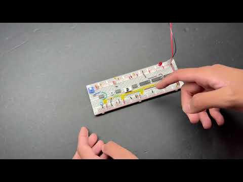
This Clock Module controls and coordinates CPU functions with other integrated chips. You can adjust the clock speed by turning the blue variable resistor at the top left. The clock can be halted using the on-on switch in the middle. You can step the clock by pressing on the tact button to the left of the switch to debug and step it in case of problems. Faster LED flashing means higher clock speed. Being able to control the clock speed is important because we want to be able to step through the program one clock signal at a time. I also learned about the concepts of rising and falling edge of the computer clock signal.


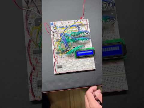
This is a computer powered by the 6502 CPU. Timing for the computer is provided by the clock module described above. The phrase "Hello, world!" is printed through assembled code loaded onto the EEPROM which interfaces with the 6502 CPU. Versatile Interface Adapter is then interfaced with 6502 to execute the code that prints "Hello, world!" to the LCD display.

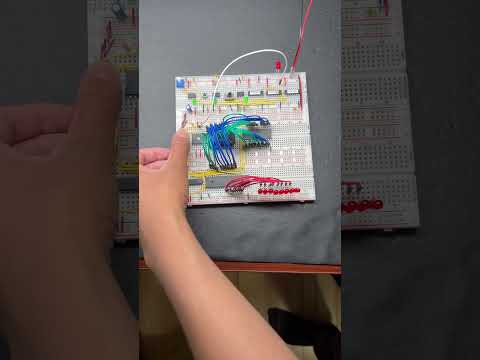
This adds two 4-bit binary numbers to produce another binary number. At the top there are three logic gates (AND, OR, Inverter from left to right) built using bi-polar transistor. In the middle there are the same logic gates built using integrated chips that are controlled by switches as inputs. At the bottom is the 4-bit adder itself. The adder is comprised of multiple gates taking in two switches with four inputs. From there, a flashing LED would mean 1, while a non-flashing LED would mean 0. In the photo above, the binary numbers 1010 (10) and 1010 (10) are being added together to produce 10100 (20).


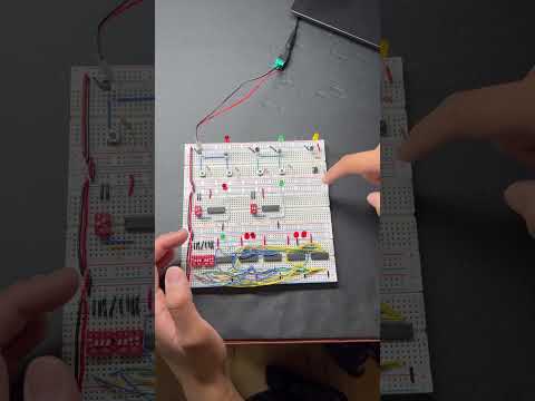
This produces a pattern in the LED's through the VIA (Versatile Interface Adapter). Again, timing for this computer is provided by the clock module above. The different light patterns show if the VIA is reading from 6502 data bus. The pattern themselves are written using Assembly language.