
PIC16F877A based 5V/20MHz development board and PIC programmer
[!] This is a discontinued project. [2016] Documents are published in order to help people that want to create similar projects or think of new ideas.
Programming Microchip's PIC (peripheral interface controller)'s and preparing electronic circuit board takes time and also inconvenient in circuit testing process. In other words, using the appropriate PIC programmer and creating the proper circuit board according to desired PIC's datasheet is not practical for situations that needs quick actions like prototyping. In addition to that there is platforms like Arduino, so PIC is not preferable except embedded applications.
Therefore, idea behind this project is creating a development board/prototyping platform using PIC.
Sprut is a project that aims to produce PIC programmer hardware with serial, parallel and USB techniques. (see Brenner) Sprut Brenner is a preferred and common programmer board for universal PIC applications.
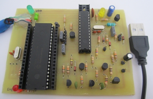
Brenner board that I was using:
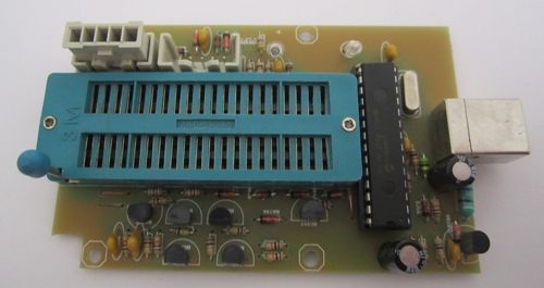
There is a 40 pin programmer on board for supporting most of the PIC's. The board itself uses PIC18F2550 (see datasheet) for communication with software.
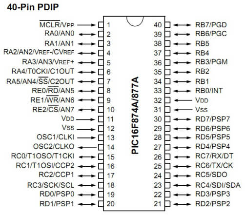
PIC16F877A (see datasheet) is a 40-pin microcontroller which is used frequently on PIC domain. (It has 256 bytes of EEPROM, 2 PWM 10-bit, ICD etc.) This features of 877A was the main reason for my decision to use this microcontroller in this project.
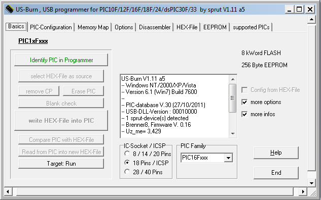
In order to load your program to PIC (which is called flashing hex file) you have to use a software called US-Burn. US-Burn also supports various features such as flashing bootloaders, changing PIC configurations and disassembler. It has Windows and Linux support.
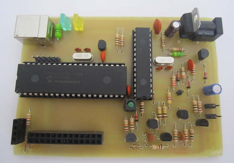
Basically if we replace the 40 pin programmer with 877A (or another PIC), put pins in order (like Arduino) and write a custom IDE with flashing features, we will have a 5V - 20MHz 877A-based development card. I'd like to call it PICasso.
Purpose of this version is seeing how easily can I use 877A's pins with the board above.
● PIC16F877A
● 7805
● 1K & 220
● LED
● 4MHz crystal osc.
● 2 x 22pF
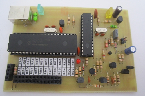
This version can be considered as the outline of the Picasso project's main idea. 18F2550 and 16F877A used together in this board with custom pins next to 877A due to testing our thesis. Eventually, F2550 which is responsible for USB communication can be used with another microcontroller on the same board and this version is open to any developments on the electronics (PCB) and the software side.
Here is the steps that followed for preparing this board:
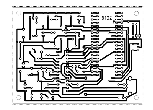
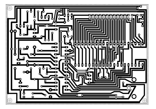
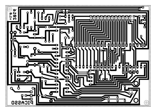
- PCB
- Circuit Part List
Same as Sprut's Brenner except PIC16F77A, 20MHz osc., 22pF's, pins and couple of LED's. So here is the c/p part list:
Part     Value			Reichelt	Conrad
===================================================
C1       220nF                 Z5U-2,5 220n
C2, C3   22p                   Kerko 22p
C4       10µF                  rad10/100
C5       47µF                  rad47/35
C6, C7   10nF                  X7R-2,5 10n
C8       100nF                 Z5U-5 100n
C9, C10  220nF                 Z5U-2,5 220n
D1 D2    BAT43                 BAT 43
D3       BZX97-3,3             ZF 3,3
IC1      PIC18F2550SP          PIC18F2550-I/SP
	 28-polige IC-Fassung  GS 28P-S
IC2      40-poliger Testsockel TEX 40
L1       680µH                 SMCC 680µ
L2       10µH                  SMCC 10µ
LED1     grün                  LED5mm2MAgn
LED2     gelb                  LED5mm2MAge
Q1       20 MHz                20-HC49U-S
Q2,Q3,Q5 BC338-25              BC338-25
Q4,Q6    BC328-25              BC328-25
R1       1k                    1/4W 1K
R2,R3,R6 10 k                  1/4W 10K
R4       4k7                   1/4W 4,7K
R5       2k2                   1/4W 2,2K
R7,R13   10k                   1/4W 10K
R8,R12   100k                  1/4W 100K
R9..R11  10k                   1/4W 10K
R14      0 (Drahtbrücke)
R15      1 k                   1/4W 1K
R16      330                   1/4W 330
SV1      ICSP                  BL 1X10G 2,54
X2       USB-B-H               USB BW
JP1      Jumper                Jumper 2,54 RT
Brenner Circuit and b8p5_partlist.txt might be helpful.
-
After preparing the circuit, there is not much left to do. We have to flash the bootloader and firmware to PIC18F2550 to use the board with US-Burn software.
To achieve this, a PIC programmer is required due to the need of bootloader flashing. -
Flash the boot_0_20mhz.hex to the 18F2550 after US-Burn detected the PIC.
-
After flashing the bootloader, put 18F2550 in your circuit and connect it's USB to your computer. Make sure everything is working with USB and circuit. (Check if any smoke coming out)
-
Start the US-Burn software. It will redirect you to firmware update section if everything goes right for you.
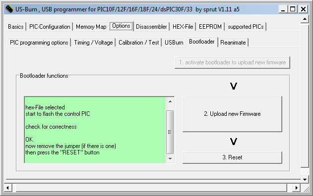
-
Select the b8_fw16.hex and upload new firmware.
-
Reset the programmer. In this point you might have to make some calibrations. So see b8_calibration_en.pdf
-
Finally put PIC16F877A in place and you are ready to go. You can flash your program (hex) into PIC and use it's pins easily just by connecting the USB.
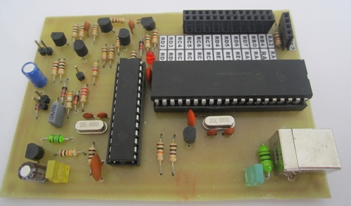
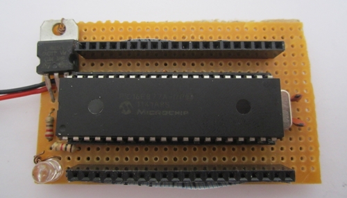
Some circuit updates were made with this version.
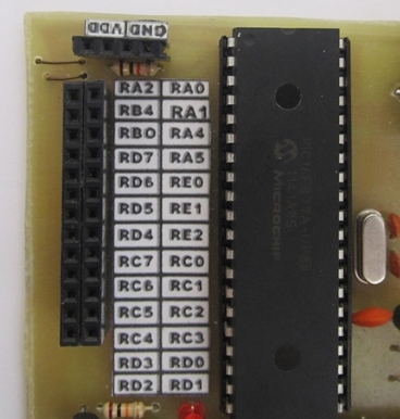
- PIC16F877A placed horizontally.
- All pins gathered in one place. Required labels added.
- PCB
- Circuit Part List
Same components with v0.2
- Instructions
Same installation/configuration procedure with v0.2
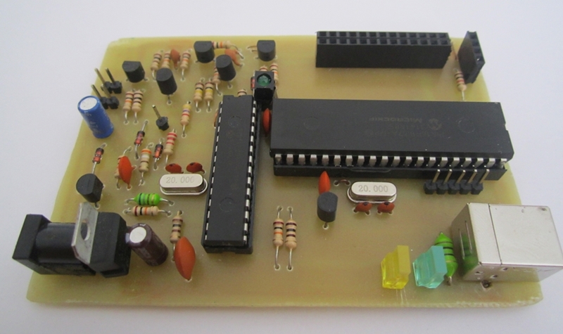
Circuit board improved and new featured added with this version.
- ICSP (In-Circuit Serial Programming) pins added for PIC16F877A.
- 5V input added to circuit with 7805 regulator.
- Some component's including LEDs position changed.
- PCB
Components and instructions are same with v0.5
-
There is no custom IDE or flashing software for Picasso. (yet?) So you have to use a third-party software like MikroC to compile your code (create hex) & flash to PIC.
-
Picasso uses Sprut Brenner's sources which is an inactive project.
Demo will be added hopefully.
GNU General Public License (v3)
Copyright (c) 2016-2023, orhun