-
Notifications
You must be signed in to change notification settings - Fork 39
JDY_08 based board documentation
- Concept
- Dimensions and range
- Function of the switch
- Wiring
- LEDs behaviour
- How to update
- Issues
- Additional info
- EasyEDA project
- Parts list
- Resources useful for making such boards
- Sale
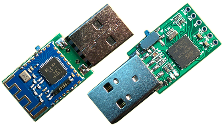
The board has 2 main parts:
- Atmega32U4 chip (the same chip found in boards like Arduino Pro Micro, CJMCU Beetle or Malduino). It is responsible for typing keystrokes.
- JDY-08 BLE module. It makes the communication between Atmega32U4 and mobile application possible.
PCB: 16x23.5mm (0.8mm thickness)
Whole device length: 39.8mm
Range: around 5 meters (see Issues for more info)
Flipping switch to "Prog" side allows the user to input "AT" commands through serial monitor in Arduino IDE. In that case switch connects pin 3 of Arduino Pro Micro to GND. When switch is flipped to "Work" side it connects GND to GND (so nothing happens).
Pin 3 of Arduino Pro Micro may be also reffered to as: SCL, PD0, pin 18 of Atmega32u4
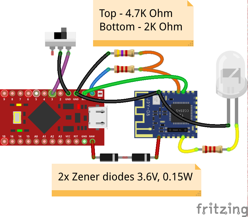
Full schematic is available at the EasyEDA project page. The wiring is equivalent to:
The blue LED shows connection status of the JDY-08 module. (LED on = connected with app, LED off - not connected).
The green LED is the "builtin led" of Atmega32U4 and lights up for 100ms whenever message was received from the mobile application (e.g. creating constant light effect when mouse is being moved)
It blinks 3 times when the switch is flipped towards the "Prog" side (showing that AT commands can be input through serial monitor if someone wishes to use them).
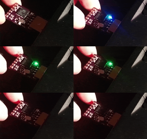
Both leds blink after pluggin-in the device (green LED showing that the code is running, blue LED showing that JDY-08 is powered).
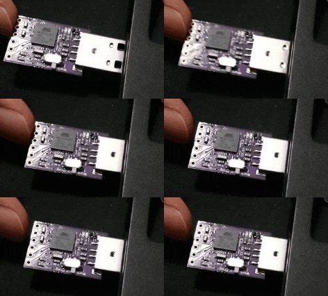
https://github.com/michalmonday/supremeDuck/wiki/How-to-update
It doesn't work with Bluetooth 4.2. Make sure to check specification of your phone if you consider using it.
Small range (up to around 5 meters) can be seen as an issue. In the first design I placed the metal header pins inder the antenna which decreased the range. Distancing the JDY-08 from the main board (see image below) increased the range to some extent.
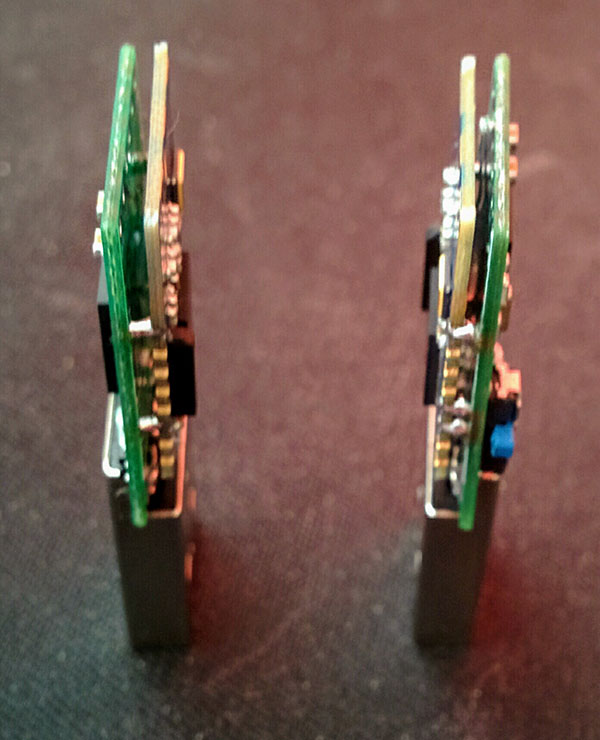
I've had problem setting the password for pairing, for that reason it is not protected by password/pin. There is option to change the password through application which will activate the password authentication (disabled by default), you can try it yourself, if it works - it works, if it doesn't and you can't connect anymore with the module then it is necessary to use AT command (AT+ISCEN0) to disable password authentication. To input that command do the following:
-flip the switch towards "Prog" side and plug-in device
-open Arduino IDE and pick "Tools->Serial Monitor"
-in the right-bottom corner pick "115200" and "No line ending"
-type "AT+ISCEN0" into the textbox near the top of the window and press enter
If "OK" appears in the main serial monitor white field then it's all good
Let me know on discord (michalmonday#3687) in case of troubles and we'll most likely fix it.
JDY-10 is smaller and works exactly the same (from the perspective of this project) as JDY-08, I'm waiting for the JDY-10 based PCB to arrive (it's smaller but doesn't have a switch).
JDY-08 module does not expect \r\n (carriage return and new line bytes) at the end of AT commands.
JDY-10 does expect \r\n.
(It means that "No line ending" option has to be picked in serial monitor for JDY-08 and "Both NL & CR" option has to be picked for JDY-10)
The default baud rate of both modules is 115200 which is perfect for "Serial1" (RX,TX) of Arduino Pro Micro.
The MO, MI and SCK pins can be used as I/O pins on Arduino Pro Micro
MO = pin 16 of Arduino Pro Micro
MI = pin 14
SCK = pin 15
The switch also can be reprogrammed to do something different, it connects pin 3 of Arduino Pro Micro with GND when it's switched towards "Prog" (it should be used as INPUT_PULLUP). For example:
pinMode(3, INPUT_PULLUP);
if (digitalRead(3) == LOW ) {
// switch_on, programming mode
}https://easyeda.com/michalmonday17/supremeduck_jdy-08

All parts are 0603.
I recommend using OSH Park, for around $3 (including shipping) it is possible to get 3 PCB copies.
It is the most expensive of the parts, you could as well buy CJMCU Beetle and desolder the chip, this way you'd also get some LEDs, 22-Ohm resistors, 1M resistor and oscillator.
- Zener diodes (2x 3.6V 0.15W MM5Z3V6)
-
Resistors
- 2x 22-Ohm (for USB data lines)
- 3x 2k-Ohm (for LEDs and voltage divider)
- 1x 4.7k-Ohm (for voltage divider)
- 1x 1M-Ohm (for Oscillator)
-
Capacitors
- 2x 1uF
- 1x 0.1uf(100nF)
- Mini switch (#DSC0011)
This switch became hard/expensive to get. I added design with alternative switch that is cheap and common (MSK-12C02)
- Oscillator (16MHZ CSTCE16M0V53-R0 3.2*1.3 SMD Crystal)
- USB 2.0 Male connector (it has to go deep just as the one from the link)
- LEDs (green - Atmega32U4 LED_BUILTIN, blue - JDY_08 connection status)
- toothpick (for placing solder paste on the PCB)
My website - http://monday.pythonanywhere.com/
Tindie - https://www.tindie.com/products/michalmonday/ble-badusb-jdy-08/
Test