Find the Arduino code in the tesla_taunte.ino file
( or here: [https://raw.githubusercontent.com/keldnorman/TeslaTaunter/refs/heads/main/tesla_taunter.ino] )
Building or using a device designed to open Tesla charge port doors via radio waves, especially one that includes a signal booster, may violate federal, state, and local laws and regulations. Such devices can interfere with wireless communications and electronic systems, leading to legal consequences under laws governing radio frequency emissions and interference. It is illegal to operate this device outside of a controlled laboratory environment or without proper authorization. Using it without a dummy load as an antenna can result in unauthorized radio transmissions, which are prohibited by agencies like the Federal Communications Commission (FCC) in the United States. By proceeding, you acknowledge that you are solely responsible for complying with all applicable laws and regulations. The creator or distributor of this information assumes no liability for any misuse or legal repercussions resulting from the construction or operation of such a device
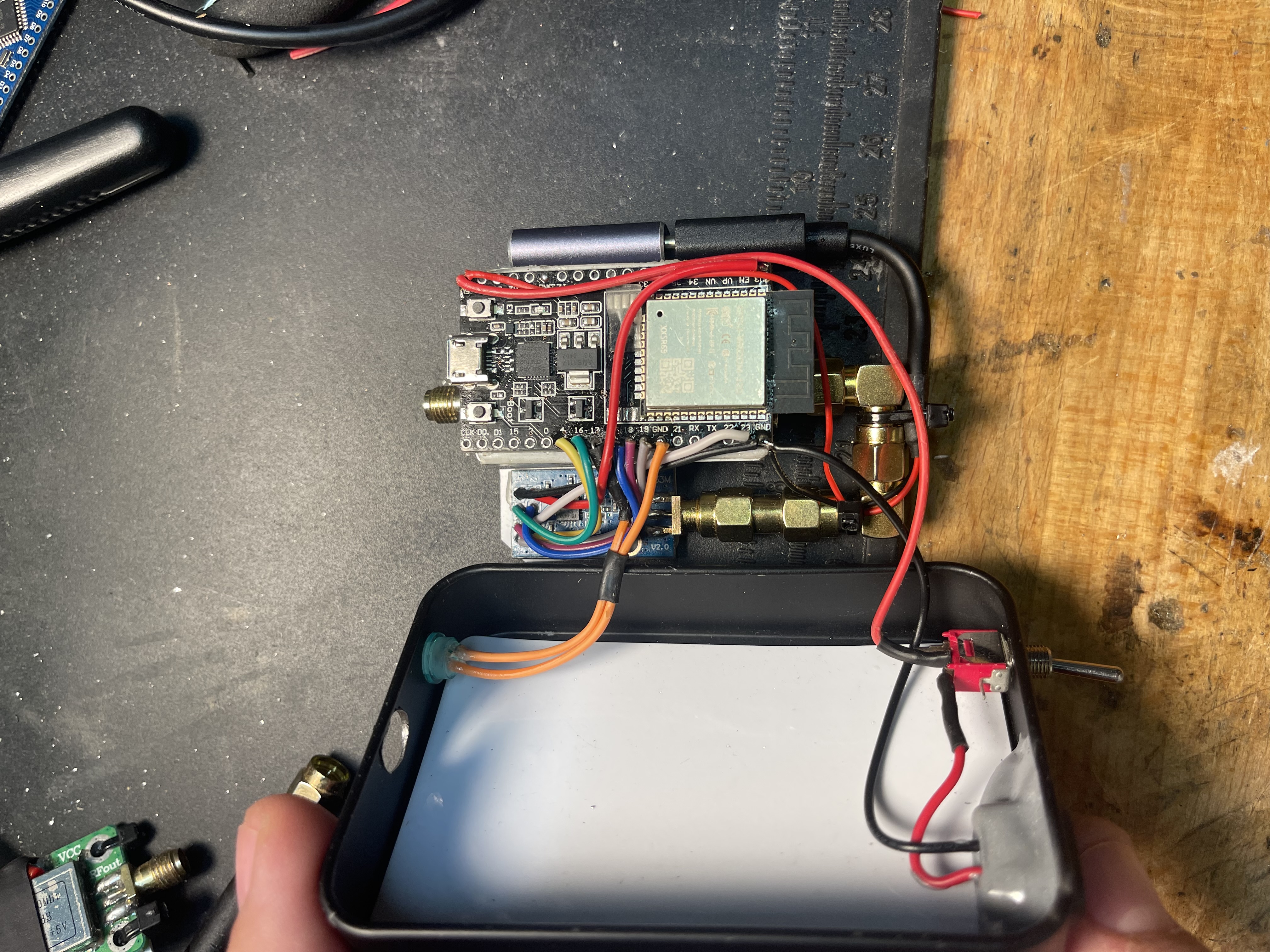
- ESP32-DevKitC core board ESP32 V4 development board ESP32-WROOM-32D/U ( Model D has a build-in Antenna for Wifi if you want to add functionality like remote control )
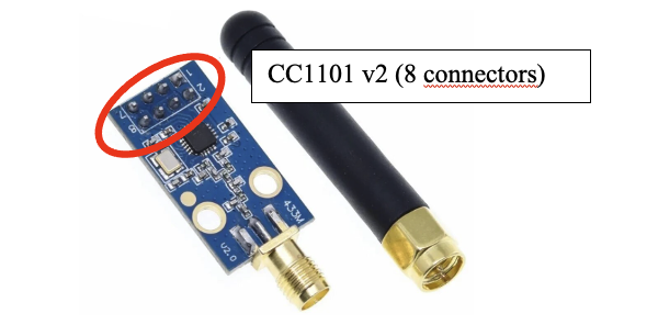
- CC1101 Wireless Module With SMA Antenna Wireless Transceiver Module For 315/433/868/915MHz ( EU uses 433 MHz and US 315 Mhz but the cc1101 can transmit on both frequencies)
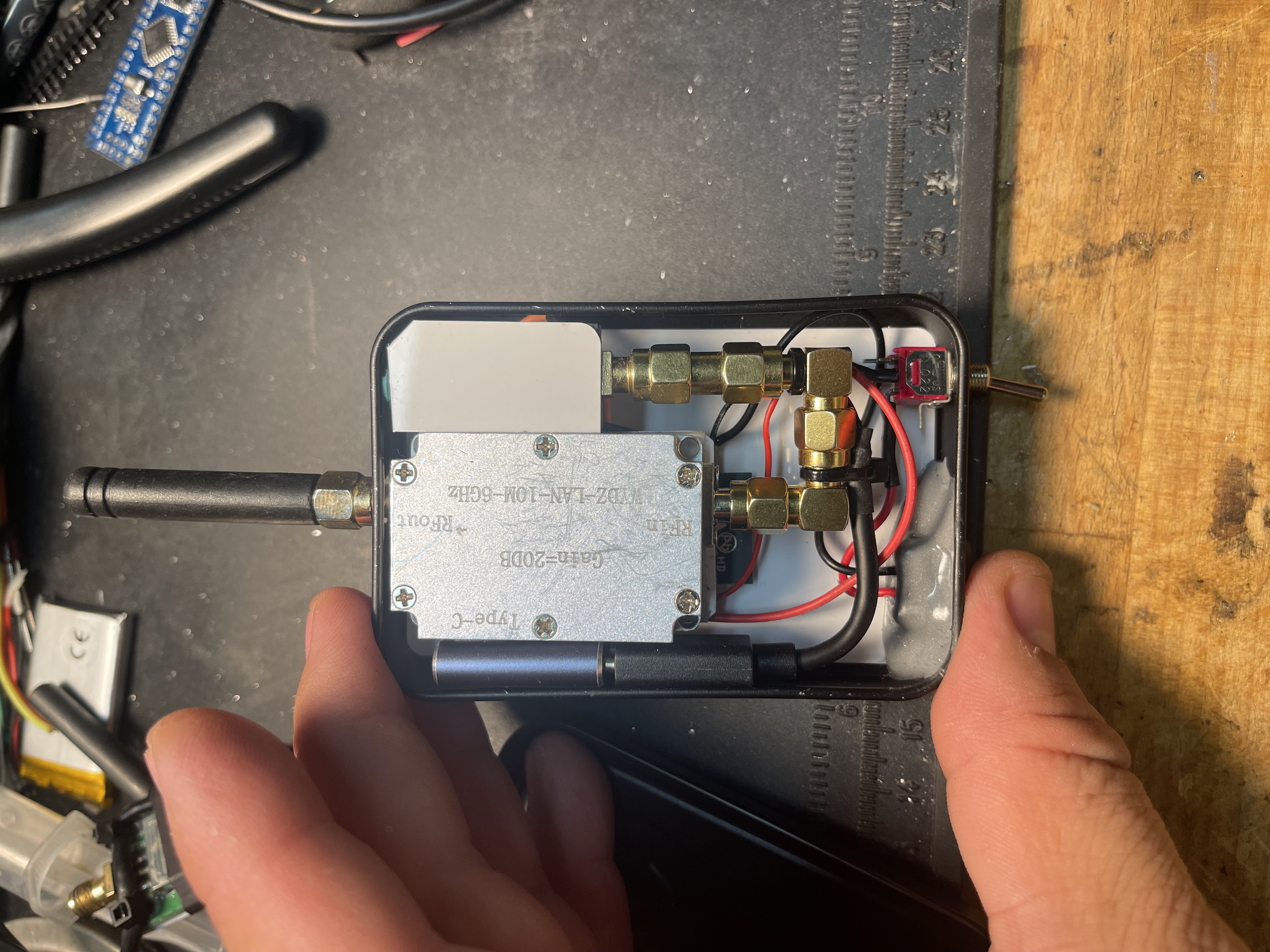
- 10M-6GHz RF Gain Amplifier either 10dB, 20dB, 30dB or 40dB High Flatness RF Power Amplifier Drive Signal Receiver Transmitter AM FM VHF UHF Radio
- 5W 10W SMA Dummy load Connector 50ohm DC-3GHZ 6G RF Coaxial Load
// Microcontroller: ESP32-DevKitC core board ESP32 V4 development board ESP32-WROOM-32D/U
//
// For more information:
//
// https://www.espressif.com/en/products/hardware/esp32/overview
// https://lastminuteengineers.com/esp32-arduino-ide-tutorial/#esp32-development-board-pinout
// https://europe1.discourse-cdn.com/arduino/original/4X/4/3/d/43d8b7d07e610d074a3a616821786e26aa7bc92f.jpeg
//
// +---------------------------+
// | __ __ __ __ |
// | | |__| |__| | | |
// | | k | | |
// VDD 3.3 Volt/ -| [3V3] +-----------+ [GND] | - / Ground (GND)
// EN/ -| [EN] | | [23] | 36 / GPIO23 / V_SPI_D / MOSI
// SENSVP/INPUT ONLY/RTC_GPIO0/ADC1_0/GPIO36/ 5| [UP] | | [22] | 39 / GPIO22 / V_SPI_WP / SCL / RTS 0
// SENSVN/INPUT ONLY/RTC_GPIO3/ADC1_3/GPIO39/ 8| [UN] | | [TX] | 41 / GPIO01 / TXD 0 / CLK3
// INPUT ONLY/RTC_GPIO4/ADC1_6/GPIO34/10| [34] | | [RX] | 40 / GPIO03 / RXD 0 / CLK2
// INPUT ONLY/RTC_GPIO5/ADC1_7/GPIO35/11| [35] | | [21] | 42 / GPIO23 / VSPI_HD / SDA
// XTAL32P/TOUCH9/RTC_GPIO9/ADC1_4/GPIO32/12| [32] | | [GND] | - / Ground (GND)
// XTAL32N/TOUCH8/RTC_GPIO8/ADC1_5/GPIO33/13| [33] |___________| [19] | 38 / GPIO19 / V_SPI_Q / MISO / CRS 0
// DAC1/RTC_GPIO6/ADC2_8/GPIO25/14| [25] [18] | 35 / GPIO18 / V_SPI_CLK / SCK
// DAC2/RTC_GPIO7/ADC2_9/GPIO26/15| [26] [5] | 34 / GPIO05 / V_SPI_CS0 / SS
// TOUCH7/RTC_GPIO17/AFC2_7/GPIO27/16| [27] [17] | 27 / GPIO17 / TXD 2
// HSPI_CLK/TOUCH6/RTC_GPIO16/ADC2_6/GPIO14/17| [14] [16] | 25 / GPIO16 / TRXD 2
// HSPI_Q/TOUCH5/RTC_GPIO15/ADC2_5/GPIO12/18| [12] [4] | 24 / GPIO4 / ADC2_0 / HSPI_HD / TOUCH 0 / RTC GPIO10
// GROUND GND / -| [GND] [C] | 23 / GPIO0 / ADC2_1 / CLK1 / TOUCH 1 / RTC GPIO11
// HSPI_ID/TOUCH4/RTC GPIO14/ADC2_4/GPIO13/20| [13] [2] | 22 / GPIO2 / ADC2_2 / HSPI_WP0 / TOUCH 2 / RTC GPIO11
// HSPI_DATA2/FLASH/D2/SD_DATA2/RXD1/GPIO09 / 28| [D2] [15] | 21 / GPIO15 / ADC2_3 / HSPI_CS0 / TOUCH 3 / RTC GPIO13
// HSPI_DATA3/FLASH D3/SD DATA3/TXD1/GPIO10 / 29| [D3] [D1] | 33 / GPIO8 / CTS 2 / HSPI_DATA1 / SD_DATA1 / FLASH D1
// HSPI_CMD/FLASH CMD/SD_CMD/RTS1/GPIO11 / 30| [CMD] [DD] | 32 / GPIO7 / RTS 2 / HSPI_DATA0 / SD DATA0 / FLASH D0
// VIN 5 Volt / -| [5V] [CLK] | 31 / GPIO6 / CTS 1 / HSPI_CLK / SD CLK / FLASH SCK
// | |
// | O | USB | O |
// | ------- |
// +---------------------------+
// ESP32 Power Pins
// ----------
//
// VIN - VIN pin can be used to directly supply the ESP32 and its peripherals, if you have a regulated 5V voltage source.
// 3V3 - 3.3V pin is the output of an on-board voltage regulator. This pin can be used to supply power to external components.
// GND - Ground pin(s) ___
// : _ :
// Transmitter: CC1101 8-pins |___|
// +-----------------+
// | | | | |
// | _ _ |
// | (_) (_) |
// | |
// | |
// | ____ |
// | | ´| __ |
// | |____| |__| |
// | |
// | O O O O |
// | O O O O |
// +-----------------+
// 2 4 6 8
// 1 3 5 7
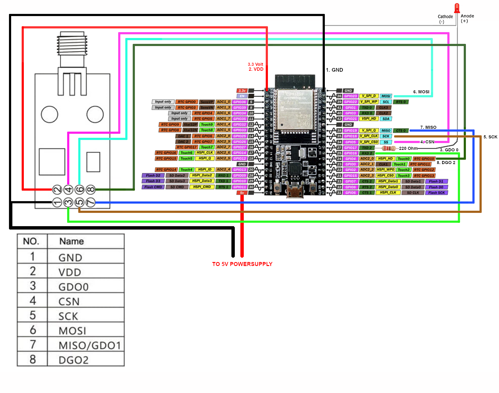
// CC1101 <-> Arduino
//------------------------------------
// 1. GND -> GND top right
// 2. Vdd 3.3V -> VDD 3.3 Volt top left
// 3. GDO0 -> [16] 25 GPIO16
// 4. CSN -> [5] 34 GPIO5 (SS)
// 5. SCK -> [18] 35 GPIO18 (SCK)
// 6. MOSI -> [23] 36 GPIO23 (MOSI)
// 7. MISO/GDO1 -> [19] 38 GPIO19 (MISO)
// 8 DGO2 -> [4] 24 GPIO4
// ------------------------------------
//
// Light emitter diode
// ------------------------------------
// On ARduino pin [17] | 27 / GPIO17 solder a 220 Ohm resistor to a LED and then from the LED to GROUND.
//
1. File -> Preferences -> Additional Board Manager URLs ->
   Add this: https://dl.espressif.com/dl/package_esp32_index.json

2. Tools -> Manage Libraries -> Search for "elechouse"
   and install SmartRC-CC1101-Driver-Lib by LSatan ( 2.5.7 or newer)

3. Tools -> Board Manager -> Search for esp32 ->
   Install esp32 by Espressif Systems (3.0.5 or newer)

4. Tools -> Select esp32 -> ESP32 Dev Module

5. Tools -> Select CPU Frequency 80 MHz (WiFi/BT)

6. Tools -> Select Flash Frequency 40 MHz

7. Tools -> Select Flash Mode -> DIO

8. Select Sketch - Upload