-
Notifications
You must be signed in to change notification settings - Fork 15
Amiga Connections
Please read Hardware Connections first, which tells you how to connect all signals to the FF OSD hardware. This page explains how to find and connect to host-machine signals on some models of Amiga.
Connections are best soldered rather than clipping to chip legs. The only possible exception are the ferrite beads at the video output, which are very easy to clip to.
It is advisable to bundle the connection wires together and mechanically secure them to the mainboard to prevent stress on soldered joints. Hot glue is a good method as it is strong but fairly easily removed if you wish to undo the modification in future.
WARNING: Be sure to secure or insulate the FF OSD hardware so that it cannot short out on the Amiga mainboard or shielding!
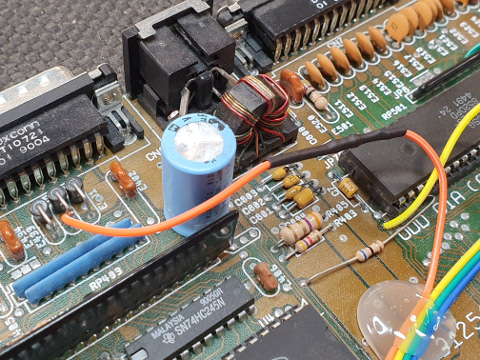
Green video out is found at the ferrite bead E432 near the video connector.
CSYNC is found at a PCB via (aka through hole) very close to U7 (CIA-A). It is quite easy to solder a wire through the via, making a strong solder joint. You can check that you have the correct via by checking for continuity to Denise pin 32 (eg multimeter "buzz test").
In the below picture the orange wire is Green and the yellow wire is CSYNC. Note the heatshrink-insulated series resistor in the orange wire.
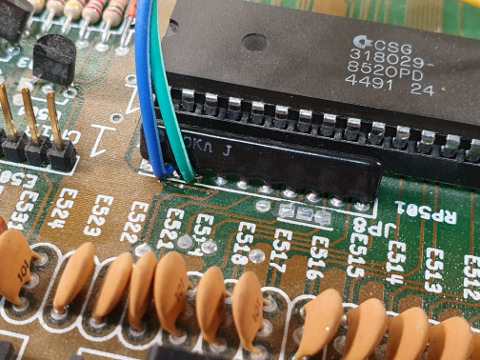
KB_DATA and KB_CLOCK are found at pins 2 and 3 of the resistor pack RP501, adjacent to U7 (CIA-A) and the keyboard connector. It is generally possible to get a soldering iron to the legs of RP501 and thus attach wires to the top of the motherboard.
In the below picture the green wire is KB_DATA and the blue wire is KB_CLOCK.
All signals are available as for Rev 6. However it may be easier to find the keyboard signals at the EMI filters introduced in this board revision, as they are often fitted less tightly to the board than RP501.
KB_DATA is connected to E631 just in front of the keyboard connector. You can solder to either side of E631, but not the grounded middle pin.
KB_CLOCK is connected to E632 immediately in front of E631. As with E631 you may solder to either side.
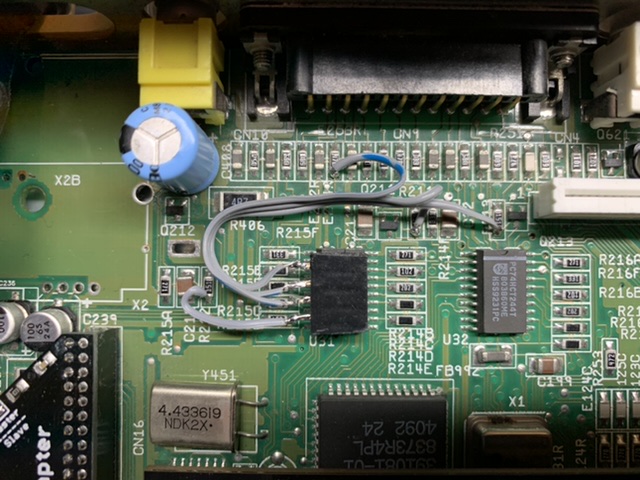
If using the A600's DB23 video connector, you can connect to the same components for keyboard, CSYNC and RGB as for A1200 Rev 1. However note that although the CSYNC and RGB components are labelled the same and in approximately the same location, they are in slightly rearranged order on the A600 so take care!
Alternative locations for the RGB signals, which work for all video outputs including composite and RF, are the non-grounded side of the following resistors:
- R211: Red
- R212: Green
- R213: Blue
These resistors are scattered near the video connector on the top side of the A600 motherboard. In the photo below the RGB signals and CSYNC are brought to a female header taped onto the A600 board.
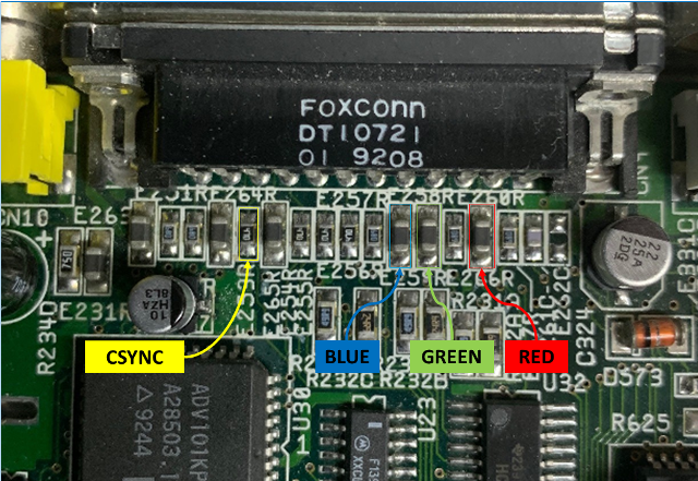
CSYNC and RGB signals are found at components near the video connector:
- E260R: Red
- E259R: Green
- E258R: Blue
- E253R: CSYNC
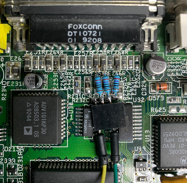
The keyboard signals are harder to solder to. They are located as follows:
- U7 Pin 43: KB_DATA
- U7 Pin 44: KB_CLOCK
Either solder direct to pins of U7, or install an upturned through-hole PLCC socket and solder to socket pins:
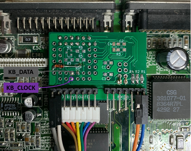
All signals are available as for Rev 1. However it is easier to find the keyboard signals at test points on CN17, which is located near the trapdoor:
- CN17.1: KB_CLOCK
- CN17.2: KB_DATA