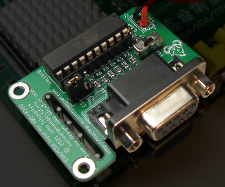
The GBS-8200 video upscaler is advertised as being able to convert CGA/EGA video to VGA, but it can't handle either without further modification. The missing pieces for being able to feed CGA and EGA video to the GBS board are the following:
- The GBS board accepts analog RGB video signals from 0V to 1V, while CGA and EGA video signals are digital with TTL logic levels.
- The GBS board can only use combined H+V sync, while CGA and EGA have separate horizontal and vertical sync signals.
- EGA modes use a 21KHz horizontal scan rate, which the GBS board does not accept.
This project only tackles the first two items on the list, which are sufficient for successfully converting CGA to VGA with the GBS-8200. If you wish to make the GBS-8200 accept EGA frequencies, you will need something like this: https://github.com/ramapcsx2/gbs-control in conjunction with this input board.
Copyright (C) 2021 John Tsiombikas [email protected]
The CGA/EGA input board is a free hardware design. Feel free to use, modify, and/or redistribute it under the terms of the GNU General Public License v3, or at your option any later version published by the Free Software Foundation. See LICENSE for details.
Schematic: http://nuclear.mutantstargoat.com/hw/gbs-cgaega/gbs-cgaega-schem.pdf
The CGA/EGA input board is a small daughterboard, which plugs directly over the 8-pin video input connector of the GBS-8200, and is powered by the GBS board through the 2-pin power connector at the top-right of the board.
The CGA/EGA input board is comprised of a cheap programmable logic chip (GAL16V8), and a simple resistor network for digital to analog conversion.
The GAL chip is programmed with the logic equations in cgaega.pld to:
- Combine the H and V sync signals to combined H+V sync.
- Convert the CGA (RGB + intensity) TTL signals, to EGA-compatible (RrGgBb) TTL signals.
- Detect the CGA dark yellow, and correct it to brown.
The last two items are only enabled when the CGA/EGA switch is set to CGA input.
- 1x GAL16V8 programmable logic chip.
- 1x IC socket for the GAL (10pin DIP).
- 1x Female pin header connector 1x8 pins, 2.54mm pitch.
- 1x JST 2.54mm pitch male pin header (optional).
- 3x 470 ohm resistors SMD 0805.
- 3x 680 ohm resistors SMD 0805.
- 1x 4.7k ohm resistor SMD 0805.
- 1x 0.1uF capacitor SMD 0805.
- 2x through hole 3-pin SPDT PCB-mounted mini switches 2.54mm pitch. Alternatively 3-pin single row pin headers can be used with jumpers.
- 1x D-SUB 9-pin female connector, PCB-mounted.
You will also need an appropriate D-SUB 9-pin cable (male to male) to connect the CGA/EGA video card to the input board. A straight through (not null-modem) serial cable can be used, but make sure it's fully wired; some serial cables carry only the Rx/Tx signals and ground, and are not suitable.
For the power lead, you can solder the 2-pin power cable which comes with the GBS-8200 board directly to the input board and plug it into the GBS power connector. Alternatively you can install a JST 2-pin connector on the input board, and make an appropriate cable with JST female connectors on both ends.
To build a CGA/EGA input board:
- zip the contents of the
gerberdirectory and send it to a PCB fabrication service of your choice (popular choices are jlcpcb and pcbway). - Acquire the necessary components (see Bill of Materials section).
- Assemble the board, and program the GAL chip with the included pre-compiled
cgaega.jedfile.
A cheap EEPROM programmer like the TL866 can be used to program the GAL.
If you wish to build the JED file from the cgaega.pld source, you'll need
GALasm (https://github.com/daveho/GALasm). Unfortunately GALasm is not free
software; if you can suggest a free software alternative, please let me know!
When you have everything set up, simply type make.
