Getting started on the Ch55x the easy way. Forked from Sduino project, also based on ch554_sdcc project
Ch55xduino is an Arduino-like programming API for the CH55X, a family of low-cost MCS51 USB MCU. The project tries to remove the difficulty of setting up a compiling environment. Users can simply write code in Arduino IDE and hit one button to flash the chip to get code running. No configuration or guesswork needed.
CH551, CH552, CH554, may be the lowest part count system that works with Arduino. The minimal system only requires one chip, 2 decoupling capacitors, and one optional pull-up resistor. These features made it ideal for DIY projects.
At this moment the project is still working-in-progress. Support most Arduino functions (Except pulse, shift, tone). Refer to examples in this repo for more info.
Automatic IDE integration is supported via the Arduino Boards Manager. This is the recommanded way of installation now.
Start the Arduino-IDE. In File->Preferences, Settings tab, enter
https://raw.githubusercontent.com/jobitjoseph/CH55XDuino/main/package_ch55xduino_mcs51_index.json
as an Additional Boards Manager URL.
- Open Tools->Board:...->Boards Manager
- Find Ch55xduino by typing 'ch' into the search line
- Click on the list entry
- Click on Install.
Now you should find a new entry CH55x Boards in the list at Tools->Board:...
- Choose CH552 Board from the list
- open the standard Blink example from File->Examples->01. Basics->Blink
- Change pin number in Blink example. For example, if you have LED on P3_0, you will write pin 30.
- compile it by hitting Verify
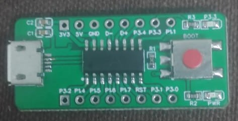
- If your board is never used with ch55xduino before, you need to make the ch55x chip enter bootloader mode. You need to disconnect USB and unpower ch55x, connect the pull-up resistor on D+ line (generally a 10K resistor between D+ and 5V, controlled by a push-button or adjacent pads). Then you connect USB. and hit Upload. Also, a blank new chip will enter the bootloader automatically.
- If you have used ch55xduino once and your code doesn't crash the USB subsystem, you can simply press Upload. Arduino and the firmware will kick the chip into the bootloader automatically.
Ch55xduino supports both USB and Serial upload methods. If the USB port of the CH55x chip is connected to a host computer, the USB method is recommended.
It is also possible to upload via serial on UART1 of CH55x chips (except CH551). To set CH55x into bootloader mode automatically, you can connect RTS or DTR of a serial adaptor to an interrupt pin of CH55x with a capacitor, and add bootloader jumping code in the interrupt handler.
If you want to leave the bootloader, you may send the following bytes at 57600 baud. 57 AB A2 01 00 01 A4
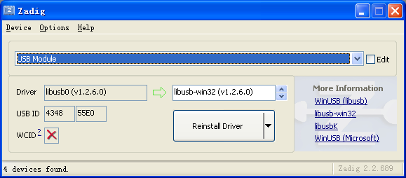
Zadig is the recommended tool to install drivers in Windows. The bootloader (4348,55E0) should be installed with libusb-win32 driver (WinUSB driver may not work on some computer).
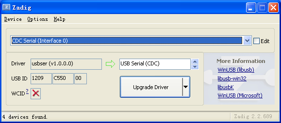
You can use USB Serial (CDC) driver for the default CDC USB stack (1209,C550).
If you tried to emulate another type of USB device without changing the PID/VID, you may need to uninstall the device before installing a new driver.
By default, Linux will not expose enough permission for Arduino to upload the code with the USB bootloader. Copy 99-ch55xbl.rules in this repo to /etc/udev/rules.d/ and restart your computer. Otherwise, the upload tool may not find the bootloader device.
Regular Arduino uses continuous numbers to code pins on AVR chips. In my opinion, it makes more sense since AVR uses letters as a port name. But MCS51 core uses numbers as port names. So CH55xduino's pins using the following rule.
PortNumber*10+PinNumber
For example, P1.1 is 11, P3.2 is 32.
CH552 has an 8-bit, 4 channel analog-to-digital converter on pin P1.1, P1.4, P1.5, and P3.2. So the input range is 0~255, not 1023.
By default, all pins on the MCS51 microcontrollers have internal pull-up resistors enabled. You may need to use pinMode to set the pin to INPUT to disable the pull-up resistor.
There is no Analog Pin definition such as A0. Just use 11, 14, 15, or 32 for their analog input feature.
There is no free C++ compiler for MCS51 chip, we can not use polymorph functions. So you can not expect the compiler will choose a function according to the parameter's type.
The biggest difference may be the Serial.print function. Here is what you should do in CH55xduino
| datatype | Print on USB | Println on USB | Print on UART0 | Println on UART0 |
|---|---|---|---|---|
| int | USBSerial_print_i(P) | USBSerial_println_i(P) | Serial0_print_i(P) | Serial0_println_i(P) |
| unsigned | USBSerial_print_u(P) | USBSerial_println_u(P) | Serial0_print_u(P) | Serial0_println_u(P) |
| float | USBSerial_print_f(P) | USBSerial_println_f(P) | Serial0_print_f(P) | Serial0_println_f(P) |
| float with precision | USBSerial_print_f(P,Q) | USBSerial_println_f(P,Q) | Serial0_print_f(P,Q) | Serial0_println_f(P,Q) |
| char | USBSerial_print_c(P) | USBSerial_println_c(P) | Serial0_print_c(P) | Serial0_println_c(P) |
| char * (str) | USBSerial_print_s(P) | USBSerial_println_s(P) | Serial0_print_s(P) | Serial0_println_s(P) |
| char array with length | USBSerial_print_sn(P,Q) | USBSerial_println_sn(P,Q) | Serial0_print_sn(P,Q) | Serial0_println_sn(P,Q) |
| int with base | USBSerial_print_ub(P,Q) | USBSerial_println_ub(P,Q) | Serial0_print_ub(P,Q) | Serial0_println_ub(P,Q) |
They are defined in Arduino.h.
Unlike most modern architectures including AVR, MCS51 has 2 RAM regions, internal data memory, and external data memory. For CH552, the internal one is only 256 bytes, and the external one is 1024 bytes.
CH55xduino uses the default Small Model for SDCC memory models. The small memory model will allocate all variables in internal, directly addressable RAM by default. Variables stored in external RAM must be declared with the xdata or far keyword.
CH55xduino also put the stack in internal RAM. So there isn't much space left for variables. If your variable doesn't need fast access, use __xdata when you declare it.
For example, if you are trying to allocate a lot of space in internal RAM.
uint8_t testArr[128];
You will trigger an error. ?ASlink-Error-Could not get 130 consecutive bytes in internal RAM for area DSEG. This can be avoided by using
__xdata uint8_t testArr[128];
For the default Arduino setting, 148 bytes are reserved for USB endpoints. There will be 876 bytes usable for external RAM.
You can see the memory mapping by opening the map and mem file generated along with the hex file.
Note that when some function is called from an interrupt service routine it should be preceded by a #pragma NOOVERLAY (if it is not reentrant) . A special note here, int (16 bit) and long (32 bit) integer division, multiplication & modulus operations are implemented using external support routines developed in ANSI-C, if an interrupt service routine needs to do any of these operations then the support routines (as mentioned in a following section) will have to recompiled using the --stack-auto option and the source file will need to be compiled using the --int-long-rent compiler option. src
With SDCC, interrupt service routine function prototypes must be placed in the file that contains main ( ) in order for an vector for the interrupt to be placed in the the interrupt vector space. It's acceptable to place the function prototype in a header file as long as the header file is included in the file that contains main ( ). SDCC will not generate any warnings or errors if this is not done, but the vector will not be in place so the ISR will not be executed when the interrupt occurs. src
Unlike AVR chips, CH55x will reset when the RST pin is High. The reset pin may be configured as an input pin. But such configuration requires modification of Configuration Information byte, which require an external tool to do so.
.
Most parts of the Arduino core system and some Arduino libraries are already ported to C-syntax. The resulting API is still very close to the C++ version and porting an existing application is not hard. Refer to the examples that come with the libraries.
- SPI: Real hardware-SPI up to 12MHz.
- TouchKey: Internal 6-channel capacitive touch module wrapper with an adaptive baseline algorithm.
Since there is no free C++ compiler for the MCS51, it is impossible to do a full 1:1 port of the whole enviroment as is has been done for the STM32 and the ESP8266.
This is not a drop-in replacement for an AVR, but thanks to some C preprocessor magic the programming API is still very, very similar and it is often enough to just move over the opening bracket of the class instanciation statement and to replace the dot in a method call for an underscore. Check the migration guide for an overview.
Arduino IDE versions 1.8.12 are tested, but most versions >=1.6.6 should work.
-
Windows: Tested on Windows 7 and XP.
-
MacOS: Tested on 10.14.
-
Linux: Tested on Ubuntu 20.04 LTS.


