A Collection of Notes from Computer Architecture using ARM Assembly on the Raspberry Pi. (Saddleback Community College, CS3B)
All credit to Brandon, who wrote most of these notes and allowed me to share them here.
"Under no circumstances is Barnett to teach directly from this material. Seriously dude, learn your own material. Study my notes if you have to, but teach it yourself."
Somewhere in the middle of the semester, Barnett had us install GEF to use on top of GDB, which gives us a lot more tools and information for reading the state of our programs during testing. For posterity's sake, I'm reposting the instructions from last semester to install GEF here, though it shouldn't be done until it's needed in case Barnett changes the instructions this time around:
1)   sudo apt-get install python2.7-dev
2)   sudo apt-get update && sudo apt-get install checkinstall
3)   sudo apt-get install texinfo
4)   wget http://ftp.gnu.org/gnu/gdb/gdb-8.2.tar.xz
5)   tar -xf gdb-8.2.tar.xz
6)   cd gdb-8.2/
7)   ./configure  --with-python
8)   make
9)   sudo checkinstall
10)  sudo dpkg -r gdb
11)  sudo dpkg -i  [name of your .deb file here]
12) sudo apt-get install -f .global _start
_start: mov R0,#78
mov R7,#1
svc 0
.endStarting from the top, we have the .global directive. When you assemble (with the as command) and link (with the ld command) an assembly program, the .global directive tag tells the linker where the program should start when everything is put together. Later on, you'll use it to tell the linker the name of a function that can be called by other files. _start is the "main" function in programs that are assembled and linked as you are probably oing now. Later on you'll compile with gcc, and instead of putting _start, you'll put main.
_start: is the name of the "main" routine (or, function,) that our program will run in. You can define more subroutines by putting any name followed by a colon before any line of formal code, but it's something we won't get into for a couple weeks.
mov is the most basic instruction you'll be using, and is used to "move" values into registers. The mov command takes two arguments: the target register you want to move a value into, and the value you want to move into the register. The first operand must be the register you are moving a value into, while the second operand can be any register or value. Values must be preceeded by a # symbol, while registers are preceeded by an R. The Raspberry Pi has 16 registers to work with - the last 3 are reserved for purposes you'll soon learn about, but you can use R0~R12 in any way you want. In this example, we've moved the decimal value of 78 into register 0.
We do another mov operation, this time moving a 1 into register 7. Register 7 will hold special importance to us throughout the semester, as it is the register the system will read from to determine what system call to run when the svc command is used on the next line.
svc is the Supervisor Call instruction, which tells our program to access system resources on the operating system in order to accomplish some task. What task it will accomplish is determined by the contents of register 7. In this case, Register 7 is set to 1, which is the code used in order to safely exit a program. When exiting a program, it will generate a code number based on the contents of R0, which can be read by calling echo $? in the linux terminal after your program finishes.
Lastly, the .end tag denotes the end of your file. You can leave it out if you want.
TL;DR: .global _start must go above your _start routine in order for the linker to know where to start your program.
_start: must go before your code to define the "start" of your program code
mov is used to move a value into a register, be it a literal value or a value from another register. The first operand must be the register you are moving a value into, the second operand can be a register or a value. Values begin with #, registers are denoted with R followed by a number.
Assemble and Link by calling your main routine _start and use the following commands:
as -g -o <objectname>.o <sourcename>.s
ld -o <executablename> <objectname>.o
or, Compile by calling your main routine main and use the following command:
gcc -g -o <executablename> <sourcename>.s
svc 0 will do something depending on what's in R7. For now, just make sure R7 is set to 0 before you run this, since this will end the program.
.end denotes the end of your program file and is optional.
Also, the comment symbol in ARM assembly is @ .
In order to set up your program to run off of GDB, you need to assemble it with the -g flag set. -g generates debug information necessary for GDB to run correctly.
Those who are assembling and linking with the as and ld commands, run your as command like so:
as -g -o <objectname>.o <sourcename>.s
Those who are compiling with gcc, run your gcc command like so:
gcc -g -o <executablename> <sourcename>.s
From here, once your program is fully compiled (that means after running the ld command, those of you who are
linking!) you can run GDB (and GEF, if you have it installed) like so:
gdb <executablename>
To debug with GDB, the first thing you need to do is set a breakpoint for your program. If you're using nano, you can
find what line you're on by using CTRL-C (or you can always display it by running nano with the -c flag). In GDB, you
set a breakpoint with
b <linenumber to break on>
When you're ready to run your program, you can do so with the r or run command. This will run your program all the way up to the next breakpoint.
If you reach a breakpoint and want to continue line by line, you can do so with the s or step commands.
When you reach a breakpoint, you can display information about your registers by running the i r command. i stands for information, and r stands for registers in this context. You'll be using this command the most when debugging in this half of the semester. You can also run i b to dump all breakpoint information.
If you see any reason to do so, you can load new values into registers with the set command. The proper format to
set a register's contents is as follows:
set $r0 = 5
where in the above example, register 0 is being set to 5.
You can list your source code by using the l or list command.
When you're done debugging, use q or quit to exit GDB.
The Current Program Status Register (CPSR) stores significant information regarding your program and the results of operations that your program carries out. Specific bits on the register are pre-defined to carry special meaning which is often used in conditional statements, depending on if they are set to 1 or 0.
The CPSR "flags" that are important to us reside on bits 28, 29, 30, and 31 of the CPSR, and are called "raised" if the relevant bit is set to 1, or "lowered" if the bit is set to 0.
Bit 28 is the Overflow flag (named V), and is raised when an executed instruction results in an error (often an unexpected change in positive/negative value due to two's compliment being triggered by a register overflow)
Bit 29 is the Carry flag (named C), and is raised when an executed operation results in a "carry". According to the ARM infocenter, unsigned overflows in addition raise the flag, unsigned underflows in subtraction raise the flag, and most importantly in the near future, the last shifted-out bit in shift operations will become the flag.
Bit 30 is the Zero flag (named Z), and is raised when an executed instruction results in zero.
Bit 31 is the Negative flag (named N), and is raised when an executed instruction results in a negative value. In
register-to-registermov operations, this can mean that a negative value was moved from one register to another.
The other bits are largely unimportant to us; Bits 04 define the mode field, Bit 5 defines the THUMB execution state,
Bit 6 is the FIRQ mask bit, Bit 7 is the IRQ mask bit, and 827 were never discussed last semester (but define other
things such as Endianness, cumulative saturation, if/then states for THUMB, and other nonsense). To my knowledge,
you won't be tested on anything that isn't related to bits 28-31.
Note that, except in the cases of the CMP and CMN (compare and compare-negative) instructions, the CPSR will
usually not change on a line-to-line basis. If you desire to update the CPSR, you must suffix your instructions with
an s. For example, the CPSR-updating equvilant of mov is movs, and the equivilant of add is adds.
Some instructions can have multiple suffixes, and having them in the wrong order can break your code. Consult the
infocenter and bugfix often to ensure that you iron out any such problems.
In the near future, you'll use the CPSR to check insturction results in order to execute conditional statements.
In GDB, you can convert numbers from one format to another by using the p/# $$$ command, where # is the letter code of what you want to convert to, and $$$ is what you're converting from.
The following letter codes will fit in #:
After p/ is the format you want to convert to, and GDB will accept the following:
x: Hex d: Signed Dec u: Unsigned Dec o: Oct t: Bin (t stands for two) a: Address c: Character constant (from ascii integer, probably) f: Float
This week we're talking about logical operations and bit shifting. Most (if not all) of you took CS3A so most of this will just be defining what instruction maps to what logical operation and where the heck the output goes.
Logical operations will take the individual bits of one register, and compare them to another register or literal number. There are three logical operations that we focus on that are out of the book: AND (logical AND), ORR (logical OR), and EOR (logical exclusive-OR); However, you also have BIC (logical AND-NOT) available to you, which is not covered in this class or the book. Bit comparisons are in order: Bit 0 in one register will be compared to Bit 0 in another register, Bit 1 to Bit 1, and so on.
All logical operations follow the same format to call them, but come in shorthand and longhand writing methods.
In shorthand, logical comparisons are written as
AND R0,#$$$$
, where R0 contains the number to compare to and is where the result of the operation is output to, and $$$$ is some
number in any format you want to compare to.
The longhand method is written as
AND R0,R1,R2
, where R0 is the register the result of the operation is output to, while R1 and R2 are the registers (or literals) to
compare.
Written below is a code example that describes what each of the logical operations will equate to in with bit combinations, and more clear tables are found in Figure 2.2 in the blue book:
@ Logical AND results 1 when both bits compared are 1
MOV R0,#0011
MOV R1,#0101
AND R0,R1 @ Results in R0 containing #0b0001

@ Logical OR results 1 when either bit compared is 1
MOV R0,#0011
MOV R1,#0101
ORR R0,R1 @ Results in R0 containing #0b0111

@ Logical EOR results 1 when only one compared bit is 1
MOV R0,#0011
MOV R1,#0101
EOR R0,R1 @ Results in R0 containing #0b0110Bit shifting operations will "push" the bits of a register from side to side a given number of spaces. This is good for multiplying powers of two or setting a register to 0 in a non-intuitive way.
As we shift bits around, you'll notice that you're "pushing bits out" at one end of the register, and "pulling bits in" at another end. What the ARM architecture does when bits are thrown out and pulled in depends on what operation you use.
Logical Shifts (LSL/LSR) will only ever pull in 0's as bits are pushed out, which means that information that
falls out of your registers due to shifting this way is lost. If you want to set a register to 0 using this kind of
shift, you'd shift over 32 spaces in any direction. Note that the last letter of the instruction (as well as in all
other shift instructions) determines the direction to shift in.
Arithmetic Shifts (ASR) will also cause you to lose information as bits fall out of your register, however the
bits pulled in will be 0 if your sign bit is 0 (if your number is positive), or 1 if your sign bit is negative (if your
number is negative). In other words, the register will try to maintain two's compliment. Note that ASL is not a
valid instruction in ARM, as it is synonymous with LSL.
Rotational Shifts (ROR) will insert bits shifted out from one end of the register into the other end of the
register. We only have right rotations in the ARM assembly language, so to perform a left shift you'll need to shift to
the right 32-n times, where n is the number of spaces to the left you would like to shift.
All shift operations are written in the following format:
LSL R0,#$$$$
@ Where R0 is the register to shift the bits of, and $$$$ is any number in any format describing how far you're shifting
 @a register. The number "format" can be bin, hex, dec, or other.

MOV R0,#0b0001
LSL R0,#2 @results in R0 containing 0b0100
A more thorough explaination on logical shift and arithmetic shift format examples,
To do a logical shift right,
LSR R0,#$$$$
Where R0 is the register to shift,
Where $$$$ is any formatted number of bits to shift (be they described in binary, hex, dec, etc)
For example,
LSR R0,#5
will shift the bits of R0 five to the right,
So if R0 held the binary value 0010 0000, it would end up having 0000 0001 after the instruction is run.
For example,
LSR R0,#9
will shift the bits of R0 nine to the right,
Assuming that R0 contained the binary value 0010 0000, running the instruction will result in R0 containing 0000 0000.
Notice how all bits shifted in were all 0's.
.
To do an arithmetic shift right,
ASR R0,#$$$$
Where R0 is the register to shift,
Where $$$$ is any formatted number of bits to shift (be they described in binary, hex, dec, etc)
In another example, assuming an 8-bit register,
ASR R0,#5
will shift the bits of R0 five to the right, and bits shifted in will copy the sign bit.
This will do the same thing as LSR R0,#5.
However, if the example used a negative five instead, the bits shifted in would be 1's instead of 0's.
Just like with logical operations, you can use a long-hand format to store your result in a different register. The format is, LSR R1, R2, R3
Where R1 is the destination register for the result, Where R2 is the register to apply the shift to, Where R3 is the register holding the number of bits to shift by, or a constant value to shift by.
Some of you might be disappointed about your first program in ARM Assembly not being some form of Hello World. I know I wasn't. That aside, today I'll be going over how you can print messages straight to the console, as well as showing you what Hello World would look like in ARM Assembly.
The first thing we need to look at is how we are going to work with Strings in Assembly, and moreover, how to store data in general. Barnett has or will say something along the lines of "datatypes don't exist in Assembly". What he means by this is that, when we use a "datatype" in ARM, we're doing nothing more than allocating a set amount of memory at an ambiguous address, the location of which is decided by the Linker during the compiling or assembling process. Memory stored is simply a series of 1's and 0's defining numbers, booleans, ascii characters, etc. It's less complicated than it sounds.
The following is an example of how to store a generic String in memory, and is separated into three parts:
exampleVariable: .ascii "Hello World!\0"
First, we have a label called exampleVariable. The label in this context is a direct reference to the first block in
memory where allocated data exists for us to access and edit as needed. Though it's not important now, you can adjust
what "address" in memory you're looking at by incrementing the label when it's loaded in code.
Next, we have a .ascii directive. Remember that directives aren't ARM instructions, rather they are used by the
Assembler to define some behavior that should be taken when processing code. In this case, we are asking the assembler
to allocate memory for a series of ASCII characters, and to convert a following String literal into their raw binary
values. There exist a number of directives for allocating data of different sizes and types:
.
.byte allocates one byte (8 bits) of memory,
.half allocates two bytes of memory,
.word allocates four bytes of memory,
.dword allocates eight bytes of memory (and stands for double-word),
.ascii allocates one byte for every character in a following String,
.asciz allocates one byte for every character in a following String, and then one more byte where a null value is
automatically placed. The null value is very important when printing Strings later in the semester, because it defines
where the end of String-allocated memory is.
Finally, we have the String literal "Hello World!\0". As you may guess, it is the text that we will eventually be
printing to the screen when we run our code. Of special note is the \0 at the end of our string. Since we chose to use
the .ascii label instead of .asciz, ARM won't auto-insert a null value at the end of our String. \0 is the null
character or null byte, and is what we call an escape character, which holds special meaning in many if not all
String interpreters that exist in assemblers and compilers. When working with Strings, you should always have a null
byte at the end of the String to define where your String formally ends in memory. When stored into memory, your String
will be visible in ASCII format. This particular String would probably look like 48 656c6c6f 20576f72 6c642100
(in HEX) when viewed in GDB using the memory viewer commands.
Now that we have that out of the way, I'll be showcasing an ARM Assembly equivalent of Hello World. The code below is not the only way Hello World could be programmed, mind you, but it shows how Strings allocated into memory can be loaded and used in a basic context.
    .global    _start
_start:
    LDR    R1,=msgtxt        @ Set R1 to point to the message to display
    MOV    R2,#13            @ Number of bytes in the message
    MOV    R0,#1            @ File descriptor code for Standard Output
    MOV    R7,#4            @ Linux service code for printing output
    SVC    0                @ Issue service call stored in R7; At this point, text in msgtxt should print
    MOV    R7,#1            @ Linux service code to exit program
    SVC    0                @ Issue service call stored in R7; Program exits here

    .data
msgtxt:    .ascii    "Hello world!\n\0"    @ 13 character message (note that all escape characters count as ONE
@CHARACTER, not two; I've also decided not to print the null byte.)
    .end
The first item of note is the LDR instruction, which can load literal data or data from an address into a Register.
Specifically, take note of the = sign placed before the String label msgtxt. = has special meaning with the LDR
command's second operand, which tells the assembler to load from an address in memory rather than a raw value. Stored at
the address given by msgtxt is the letter H, the first letter of our String.
The second item of note is also our LDR instruction, but also the next three lines following. All together, these four registers (R0,R1,R2, and R7) make up everything necessary for us to execute the Linux service for printing to an output stream. Each register has meaning that you should keep track of:
R0 contains the file descriptor, or a defined open file on your operating system. During program runtime, you have
three of these descriptors open already: Standard Input (value 0), Standard Output (value 1) and Standard Error
(value 2). If you open any more files, new file descriptors will be generated for you to use.
Since we want to write to Standard Output (the console you're running your program from), we want R0 set to 1.
Printing to Standard Input is generally a bad idea, since it is supposed to be read-only.
R1 contains the address of a character that we want to print, or the first character in a String that we want to
print.
R2 contains the number of characters to print, or the length of the String you want to print. Putting a 1 here
means that only the character at the loaded address gets printed, however adding any more to this value will print more
characters by adding one to the address stored in R0 and printing that address's contents, until the size of the
String defined in R2 is reached. For now, this means that you can only print Strings of a size which you already know,
but automating checks for variable String sizes isn't hard once you get the hang of ARM programming.
R7 contains the service call, as you already know, and in this context must be 4 so the print service can be called
from Linux.
Finally of note is the .data directive, which is used to define a section in our code where labels to data in memory
are defined. This section exists outside our section of executing code.
Below is a brief example on the use of STR, which is LDR's counterpart. STR will store values into specified
blocks of memory. This allows you to manipulate Strings and other values during runtime, or as you'll see soon, enables
you to preserve register contents while working through subroutines.
LDR    R1,=msgtxt
STR    R0,[R1]
The above code will store the value of R0 into the address defined by R1. The square brackets in STR's second operand
hold special meaning, telling the Assembler that it should expect and work with a memory address at the given Register,
rather than a raw byte value.
Say msgtxt held the String "Hello World!" and we ran the above code, while R0 held the ASCII value for "A" (which
would be 65 in Decimal).
The previous String would now read "Aello World!" after the above code executes.
I neglected to mention this before, so I will now: When using the LDR command with square brackets around the second operand, assuming the second operand contains an address, LDR will instead load the raw value that is stored at that address. The following example demonstrates how you can load a numeric value from memory:
exampleVar:    .word    64
@ ... Somewhere in _start ...
    LDR    R1,=exampleVar    @ Load the exampleVar label's address
    LDR    R1,[R1]    @ Loads the raw value stored in an address contained by R1
@ ... Runnin GDB and viewing R1 at this point should show it contains 64Looks like you're starting to write subroutines to organize your code better. I'll go over it super fast, since it seems like something easily grasped through book examples and homework prompts.
Subroutines are written very similarly to your _start or main routines, the only difference being that you don't
give them a .global directive at the top of your code unless you want them visible to every file in your project. You
can put a subroutine label anywhere in your project, be it within your main block of code in order to enable some for
of looping, or in a totally seperate area that is inaccessible to other blocks of code (due either to program ending
service calls, or due to branching commands).
To run code that follows a label, we use a branch instruction, followed by the label (or program counter address) we want to run our program from. Branch instructions take the following forms:
B subroutA @ Branches to a subroutine named subroutA
BL subroutA @ Branches to a subroutine named subroutA and appends the location of the next instruction to the link
register.
BX LR @ Branches and exchanges to an instruction stored in the Link Register, essentially returning to the instruction
immediately after a previously run BL instruction.
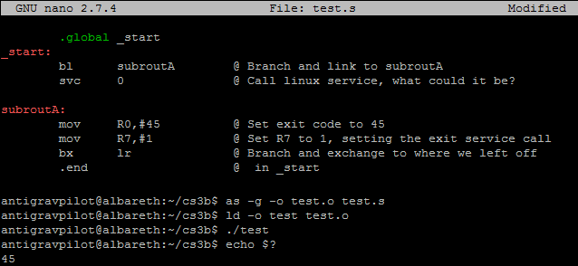
Here is an example of some basic Branching and Linking in action, in a program of similar design to the program in the first post I made here.
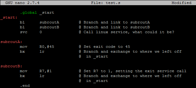
Here is another example that outputs the same exit code, this time with two subroutines rather than one.
Recently some questions have cropped up about endianness and why it might matter when we're programming. In the following post, I'm going to explain just what endianness is, what part it plays when we're programming, and how you can view data in memory so you can debug Strings efficiently with minimal confusion.
First and foremost, let's speed through some definitions: Endianness refers to the method used to store data into memory at runtime, and there are two formats that exist for ARM to choose from. To store data in Little Endian means to store the least significant byte (the "little-end") of data in the low-address of a block of memory. To store data in Big Endian means to store the most significant byte (the "big-end") of data in the low-address of a block of memory. Data is separated on a 4-byte (32-bit) basis when stored in memory, which is what I mean when I say "block of memory".
The ARM Architecture is what we call "bi-endian", meaning it is able to swap between big-endian and little-endian formats. By extension, this means that we can change the format ourselves depending on how we're implementing our code. In most implementations, ARM stores data in the little-endian format, meaning the least significant byte of a word (four-byte value) gets stored in the lowest (first) memory address of a given memory block. In plain english, Bits 0 through 4 in your register get stored in Bits 0 through 4 in memory. This might seem intuitive, but if you're trying to read Strings out of memory, you might notice some weirdness.
So let's do exactly that! In the following example, I've decided to load the starting address of a ten-byte string from memory into a register, and then print it to show that no funny business is happening on the front end. I will then show you what this looks like in memory using some new GDB commands.
.global _start
_start:
MOV R0,#1 @ Set file descriptor for printing
LDR R1,=str @ Load string from memory address from memory, the first address to print from
MOV R2,#10 @ Set length of string to print
MOV R7,#4 @ Set linux service call; print
SVC 0 @ Execute linux service; print
MOV R7,#1 @ Set linux service call; exit
SVC 0 @ Execute linux service; exit
.data
str: .asciz "Raspberry\n" @ String of length 10 (9 plus newline). Note that this string is actually of length
@11 if we are thinking about memory allocated, due to the fact that we're using .asciz, which puts a null character at
@the end of our string automatically, but since we don't print this, we say that it's of length 10.
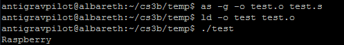
.endJust to show that this program runs as expected ...
#Reading Memory in GDB
Now that we have our test program properly loading a String, I still need to demonstrate how memory is being managed in the background. You can follow along by opening up a program of your own which loads a String, or copying the one I just posted. This section goes over the exact method I use to read memory in GDB, as well as the commands and know-how used to read it.
If you were to open my program in GDB and run it until I execute my LDR command, you will notice that R1 will point to some address in memory. For me, this is presently appearing as 0x20094. I will want to know this, since there are hundreds of thousands of memory address that I could access, yet which are also meaningless to me. This is the part of class where having GEF really starts to help you, because it will recognize Strings that are null terminated in memory which are loaded into your registers, and will attempt to read to you the String contents of that memory in a convenient manner.
To formally read the contents of your memory as they currently exist during test runtime, we use the examine, or x, command. This functions similar to the print, or p, command, but there are key differences which you need to keep in mind: Examine requires a length, a format to print in, and an address to examine. Or, if you want to only examine one block of memory in hex format, you can simply put x followed by the address to print.
The examine command takes the following format:
x/nf addr
Where n is the number of memory addresses you want to print,
Where f is the display format, which can be any of the following: x: Hex d: Dec t: Bin (t stands for two) o: Oct b: Byte (as hex, but prints one memory address rather than the entire 4-byte memory block) And a few others that we don't get into, typically.
Where addr is the starting address to examine.
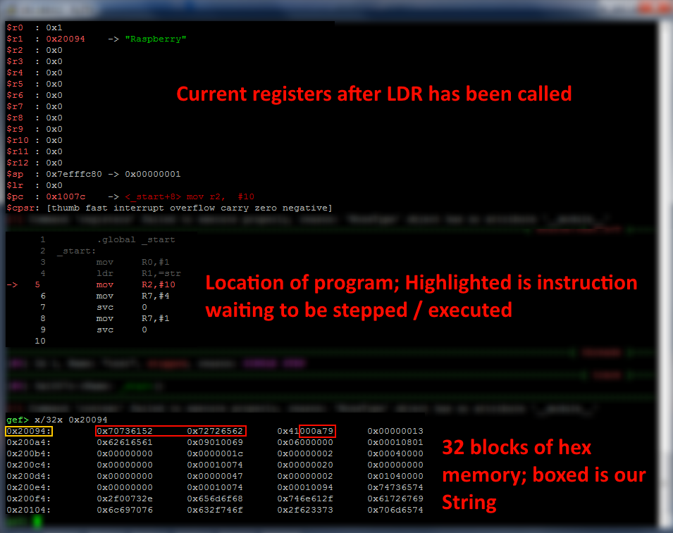
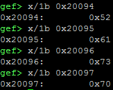
The above screenshot shows what our program looks like in GDB after the LDR instruction has been called, with our memory reading command at the bottom of the screenshot. The yellow box shows the address we're reading from, while the red boxes show our exact String. Open up an ASCII table and translate it for yourself from HEX, and you'll notice that things are indeed a little backwards!
0x70746152 is the ASCII-form in memory of the first four letters of our String, Raspberry\n\0. The hex value of 52
matches to capital R on the ASCII table. The hex value of 61 matches to lowercase a on the ASCII table, and so on. So we
read each block of memory from right to left, to determine what our String says in memory. You can also see that the
.asciz directive did print a null byte at the end of our string, so data that isn't pertinent to us is separated from
the data we're writing.
The below screenshot, which shows the printing of individual memory bytes rather than entire blocks, additionally shows
that the first byte of memory is indeed storing the first letter of our String. The lowest byte in memory, just like how
our registers are visualized to us, is on the far right in the full four-byte representations of memory contents. Also
take note of how the leading three zeroes of our memory addresses are not visible: In memory, the address we're working
with is 0x00020094, but we can leave out the lead zeroes for readability. Barnett might not give you this luxury on
your tests.
You might have run into a problem recently, if you tried nesting one subroutine in another. Since LR can only hold one
PC address to return to with the BX LR command, you'd often have to save additional return addresses to other
registers, quickly creating problems when working with multiple nested subroutines. Thankfully, ARM has this awesome
thing called the Stack, which you can push and pop register values to and from using, you guessed it, PUSH and POP
instructions.
The more straightforward use of PUSH and POP is storing the contents of your LR before and after your subroutine's main block of code. In the event that you branch and link to another subroutine, this means that the original return address to the rest of your code is still accessible after code is finished executing. You would format it like so:
exampleSubroutine:
    PUSH    {LR}    @ Push the contents of LR onto the Stack
    @ Whatever code you want to run, which can be more BL instructions
    POP    {LR}    @ Pop the last saved contents of the Stack, and save them to LR
    BX    LR
Note the phrasing of my comments - Values you save to the stack do not have to go back into the registers they came from. You can also save any register or range of registers you want onto the Stack that you want. Next described is an example of someone saving their argument registers, a couple random registers, and the LR, but then popping them into different registers before returning to a previous routine.
exampleSubroutine:
    PUSH    {R0-R3,R5,R8,LR}    @ Ranges described with a dash between two registers, commas separate singular or range
    @pushed registers
    @ Whatever code you want to run, which can be more BL instructions
    POP    {R4-R7,R8,R9,LR}    @Haphazardly popped registers to demonstrate functional popping into different registers.
BX LRSeriously? Barnett knows it doesn't work in most text editors for what we intend to use return characters for, and he wants you to use this to break lines? Headaches all around.
Long story short: Instead of 13 for your return character label, put 10, which is the proper newline character. This
will properly put your output writer onto a new line. It'll save you the trouble of figuring out why your linebreaks
don't work as intended.
... Okay, so what does the CR character actually do? A quick look at Wikipedia will tell us that it is meant to reset a device writer's "current position" during printing to the beginning of the same line of text. At best, it'll do nothing for us in RASM1, at worst it'll write over previous output and get us nowhere.
That link that Kenneth posted in #useful-links is a treasure trove of information, and has everything that I would have for the topic I said that I'd explain a while ago: All of the different control codes are there, their names and what CPSR flags they associate with are listed, good examples are present, the whole schebang. In this post I'll annotate over topics listed in the linked presentation and add in a few extra tidbits as I think of them.
In order to set up flow control, we need a means of comparing registers and values as we're working with them. As I explained in another post, albeit briefly, the *Current Program Status Register (CPSR) contains bitwise flags that change based on what instructions we are executing in our code. The CPSR's values do not change unless we want them to. There are two methods of modifying the CPSR:
Mentioned in the presentation is the use of the CMP (compare) instruction, which takes two operands: The first operand is the register to check, and the second operand is either a register or immediate value. Functionality-wise, this instruction functions exactly like SUB, except the result is discarded instead of being saved to a register, and the solution of the subtraction will be used to set the CPSR. Also of note is the CMN (compare-negative) instruction which functions instead like ADD.
Not mentioned in the presentation is the s instruction suffix. Many commands in ARM (mostly mathematical) can be
suffixed with the letter s to notify ARM to update the CPSR based on that instruction's result. For example,
ADD R0,R1 will not update the CPSR, however ADDS R0,R1 will update the CPSR.
Some examples of CPSR-setting are listed here:
CMP    R0,#5    @ Compares the contents of R0 to decimal 5
SUBS R0,#5 @ Equivilant to the above commandAwesome! We've set the CPSR and are ready to move on! ... So, what now?
The second page of the presentation presents you with a chart containing all of the conditional suffixes that ARM uses. Checking for equality is one of the most important ones, and you'll find yourself using it a lot for looping. The most often used ones are easy to memorize for the most part, since the grammar is intuitive for the most part.
For example, if R0 in the above code block contains 5, and the line CMP R0,#5 is run, the CPSR would be updated to
raise the Zero flag, since 5 - 5 = 0. However, to act on this equality, we must tell ARM to execute an instruction
only if the Z flag is raised. You can do this by suffixing the end of an instruction with eq. All together, it
would look something like this:
MOV    R4,#5    @ Move decimal 5 into R0
CMP    R4,#5    @ Compare contents of R0 to decimal 5, update CPSR
BEQ    putstring    @ If the above comparison was an equality (CPSR Z raised), run the putstring subroutine
The ability to branch between code blocks selectively now gives us amazing power over our code - Suddenly, looping is possible using basic math! Our programs can now decide what to do based on text input and run indefinitely! We can make our own line readers! The possibilities are endless:tm:! A list of conditional suffixes is described below for your accessibility:
eq    Z = 1    Equal
ne    Z = 0    Not Equal
mi    N = 1    Negative
pl    N = 0    Positive or Zero
lt    N != V    Less Than
le    Z = 1 or N = !V    Less Than Or Equal
gt    Z = 0 & N = V    Greater Than
ge    N = V    Greater Than Or Equal
hs    C = 1    Unsigned Higher Or Same
hi    C = 1 & Z = 0    Unsigned Higher
lo    C = 0    Unsigned Lower
ls    C = 0 or Z = 1    Unsigned Lower or Same
vs    V = 1    Overflow
vc    V = 0    No Overflow
al            Always True
A quick refresher on the CPSR flags:
N    Bit 31    Previous result was negative
Z    Bit 30    Previous result was zero
C    Bit 29    Previous result caused a carry
V    Bit 28    Previous result caused an overflow
In GEF (after upgrading GDB, which you should probably install very soon if you don't have it yet), you can view the CPSR as you step through your code, allowing you to more easily debug conditionals before and after code executions. If something doesn't execute the way you want it, take note of your line number and check the CPSR before and after to ensure it contains the values you expect when a conditional is reached.
Described below is an example of a basic loop, which you're free to use as you see fit. In the vain of making clear how the loop works, I've avoided a bit of shorthand in this example. Can you find a way to make this one line shorter?
_start:
    MOV    R9,#10    @ Counter / Number of times to loop
    MOV    R7,#1    @ Prepare exit code
loop:
    @ Insert any code you want to execute in the loop here
    SUB    R9,#1    @ Subtract 1 from our counter register
    CMP    R9,#0    @ See if counter has reached zero
    BNE    loop    @ Return to the start of the loop if zero is not yet reached

    @ Normally, empty space to remind me that we are writing code *after* the end of the loop.

    SVC    0    @ Exit program, or replace this with whatever you want to run after your loop.
In case Kenneth's link gets buried later in the semester, I'm reposting it here ~~ so I can bury one all by myself ~~ for you all to go back to as needed. Post any questions on the topic into any of the help chats and ping me, I'll be happy to add to this otherwise broad overview.
https://people.cs.clemson.edu/~rlowe/cs2310/notes/ln_arm_control.pdf
So, RASM3 is coming to a close, and it looks like you all will be working toward implementing Linked Lists in the
very near future. By this point, you should have a grasp over what malloc does, how you can allocate specific
amounts of memory, and how to traverse those allocated memory slots to read, write, and modify data stored within them.
With all of this in mind, you have the tools necessary to build a Linked List! By special request, I write this post
today to help explain what exactly a Linked List looks like in memory, and to give you all a jump start for work on
RASM4.
First, let's review how malloc works when called in some sample code:
mov    R0,#6
bl    malloc
@NOTE: MALLOC DOES NOT PRESERVE R0-R3
As we know, malloc is our C subroutine which is used to dynamically allocate memory during runtime. It takes in a
single argument, R0, which contains the number of bytes to sequentially allocate for use (or, in simpler terms, the
number of characters we want to have in our String). After this is done, malloc returns the first address in memory
which was allocated.
So we've allocated 6 bytes in some obscure location in memory, and R0 now contains the first address that was allocated.
Great! Through your work in the String library assignments, you would have remembered that we can store to locations in
memory using the STR instruction.
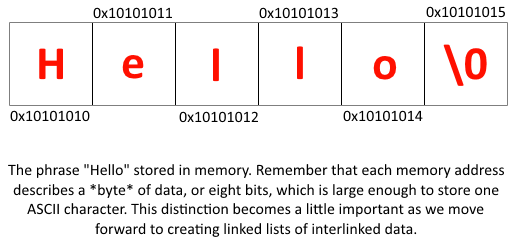
For the sake of the lesson at hand, let's pretend I've used STR instructions to store the phrase "Hello", followed by
a null byte in my allocated memory. The null byte is important for logistical reasons - We use it to denote the end of
the string, for the sake of our text printers, readers, and most importantly when reading our linked lists; since by the
time we begin reading our linked lists, we are working with Strings that we don't immediately know the size of.
Assuming R0 in the above code returned 0x10101010, my allocated memory should look like the image below, after I've
loaded the aforementioned phrase into it using STR instructions. Please note that I am not considering Endianness
with these examples.
Let's step back for a moment and talk semantics. A linked list is defined as a collection of data, where each piece of
data in the list is stored in memory non-sequentially. This means that, even though the characters in our Strings will
be defined sequentially in each use of malloc, where they go in memory between different uses of malloc is not
(and can't be) explicitly defined.
To put this into perspective, imagine that I'm trying to put a sentence into memory, but rather than write the entire
sentence into one giant chunk through one use of malloc, I decide to put each word in its own section of memory, by
using malloc multiple times. Repeating the example in the above section, I store my data into memory, and much to my
dismay the result is quite annoying to parse through.
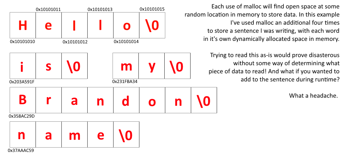
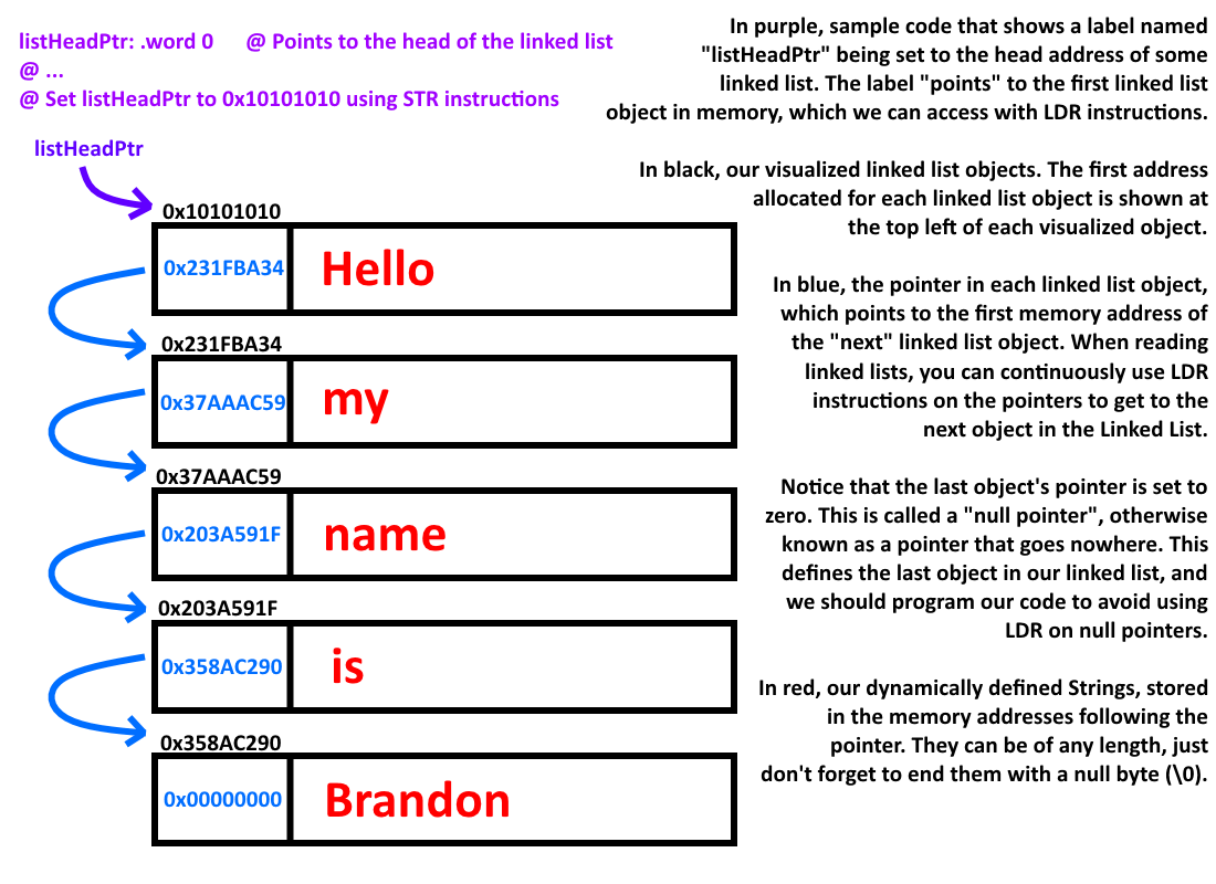
Linked Lists solve this problem by pairing each block of data with a pointer, which is assigned to the raw memory address where the next piece of data in a list is stored. By using them, we eliminate the need of having more than one label to define our many pieces of dynamically defined memory, as we now only need to know the first memory address in the list to have access to the entire list. Additionally, we now have a means of extending the amount of data we can work with at a time to hilarious proportions, where before we had to sacrifice labels and registers to the cause.
Remember earlier when I mentioned that you should remember how big a byte is? This is where that knowledge comes in handy. Bear with me for a moment; We know that a single hexadecimal digit is four bits long, and a memory address is comprised of eight of these hex digits. Doing the math, we can figure out that a memory address is four bytes long.
So if we wanted to use malloc to dynamically store the word "Hello" in memory as a Linked List object, we need to
ask malloc to allocate 4 bytes for our pointer to the next Linked List object, 1 byte for the String's null
pointer, and 5 bytes to store the word "Hello" in memory. R0 would have to be set to 10 when running malloc!
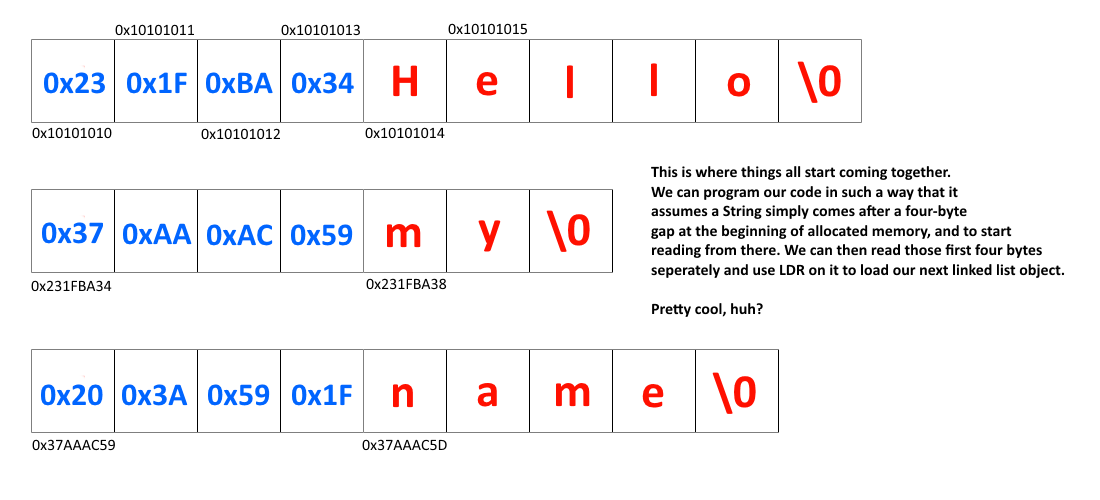
In order to read Strings in this way, we can simply build our program to assume that the first four bytes of a
Linked List object are junk, and that it should skip past them. That is, if we were to use the LDR instruction to
load up the contents of address 0x10101010 in the above example, you would add 4 to the loaded address to obtain the
first letter of your String. Assuming you are loading the address into R0, you would simply run ADD R0,#4 and have no
problems printing the String.
Bear in mind that you'll need two pointers at minimum to work with a Linked List in ARM - The first pointer will point to the address of your first Linked List object. This is called the head. The second pointer will point to the address your program is currently working with, storing it temporarily in case you need to free up your registers for some other operation.
You will also need to design functions in order to add to the "tail" (the null-pointer end) of a Linked List, to add to the middle of a Linked List, to add to the head of a Linked List, to modify data, and to delete data. All of these requirements are probably described in the RASM4 assignment.
In the way of modifying data, it is enough to simply allocate a new Linked List object, swap it out with your old one (making sure to update the current and previous pointers) and deleting the old object.
In the way of deleting objects, you can branch and link free with an address in R0 to formally free up memory that was
allocated with malloc. You don't have to worry about specifying the amount of memory to free up, it has ways of
taking care of that for you. (It probably just keeps going until it hits a null byte, but I don't know.)
And with that, you should have enough information to get started with RASM4! Do ping me in the help chats if you need clarification on some details.
AFTERWORD: It came to my attention during the third quarter of the semester that it's more helpful to think of the linked list section in terms of structs, since what I basically described was a struct. Goes to show how bad I am at vocabulary, huh?