dwdebug and pyupdi provide a covenient and cheap solution by using a standard TTL serial port to program debugwire and UPDI AVR MCU.
You can follow below circuit to make a adapter yourself, then connect it to debugwire or UPDI pin, use dwdebug and pyupdi to program and debug (dwdebug for debugwire, no opensource UPDI debug hardware solution up to now).

As I tested, it works with my ch34x and ftx232 usb to serial adapters.
For solution 1, the '4.7k resistor' can be replaced by 1k to 4.7k resistor, it depend on your serial adapter. you can test it using breadboard and find out the best resistance value you should use, 'the best' means it can establish stable connection.
For solution 2, the '1N5819' diode can be replaced by 1N914/1N4148, and some zener diodes as I tried also works very well.
According to 'UPDI High-Voltage Activation Information':
" When a high-voltage pulse is detected on the disabled UPDI pin, the pad switches its behaviour over from its previous functionality (GPIO or /RESET) into UPDI mode. However, in order to safeguard against an ESD discharge event disabling functionality in doing so, a valid UPDI key must be clocked in within a 65 ms window after the high-voltage event. Either the NVM enable key or chip erase key can be used. Once a key is clocked into UPDI, a UPDI reset must be issued for the key action to be activated. Once the reset has been processed successfully, the UPDI pin is enabled properly for that session.
In the event that a valid key is not clocked into UPDI within the window, the high-voltage event is assumed to be an ESD discharge, and the device will be reset. The functionality of the UPDI pin will once again be loaded from the fuses and user code will start to execute as expected. "
" High voltage activation for UPDI is a simple pulse, rising from Vdd to the high-voltage threshold, and falling back to Vdd. Unlike some other high-voltage interfaces, the high-voltage source plays no part in the programming of memory, it is simply an activation mechanism for UPDI physical interface. "
That's to say, what we all need to do is sending a 12v pulse before any other programming signals and then activate the UPDI pin and use it as normal UPDI, utilities such as pyupdi can be used directly without any code changes.
Here is a simple solution works with my CH341 and FT2232 adapters. the 12v pulse is sent entirely by hardware, as a result of the RTS handshaking line being asserted when the serial port is opened, and thus does not require any special support in the programming software.

The BOM list:
- one LTC1262CN8 DIP-8 or MAX662ACPA DIP-8, DC/DC converter.
- one SI2301CDS-T1-GE3 SOT-23 or IRLML6402TRPBF SOT-23, P-MOS
- one SOT-23 to 2.54 converter board, or you can find a way to solder the PMOS to board.
- two 220nF (224) capacitor
- two 1uF (105) capacitor
- one 10nF(103) or 100nF(104) or 1uF(105) capacitor, as I tested, all works.
- two 220 Ohm resistor
- one 300 to 1k Ohm resistor, used with HV LED indicator, depend on LED you use.
- three 1n914 or 1n4148 or 1n5819 schottky diode
- one 5.?V zener diode, optional, just in case.
And this is the board I made:
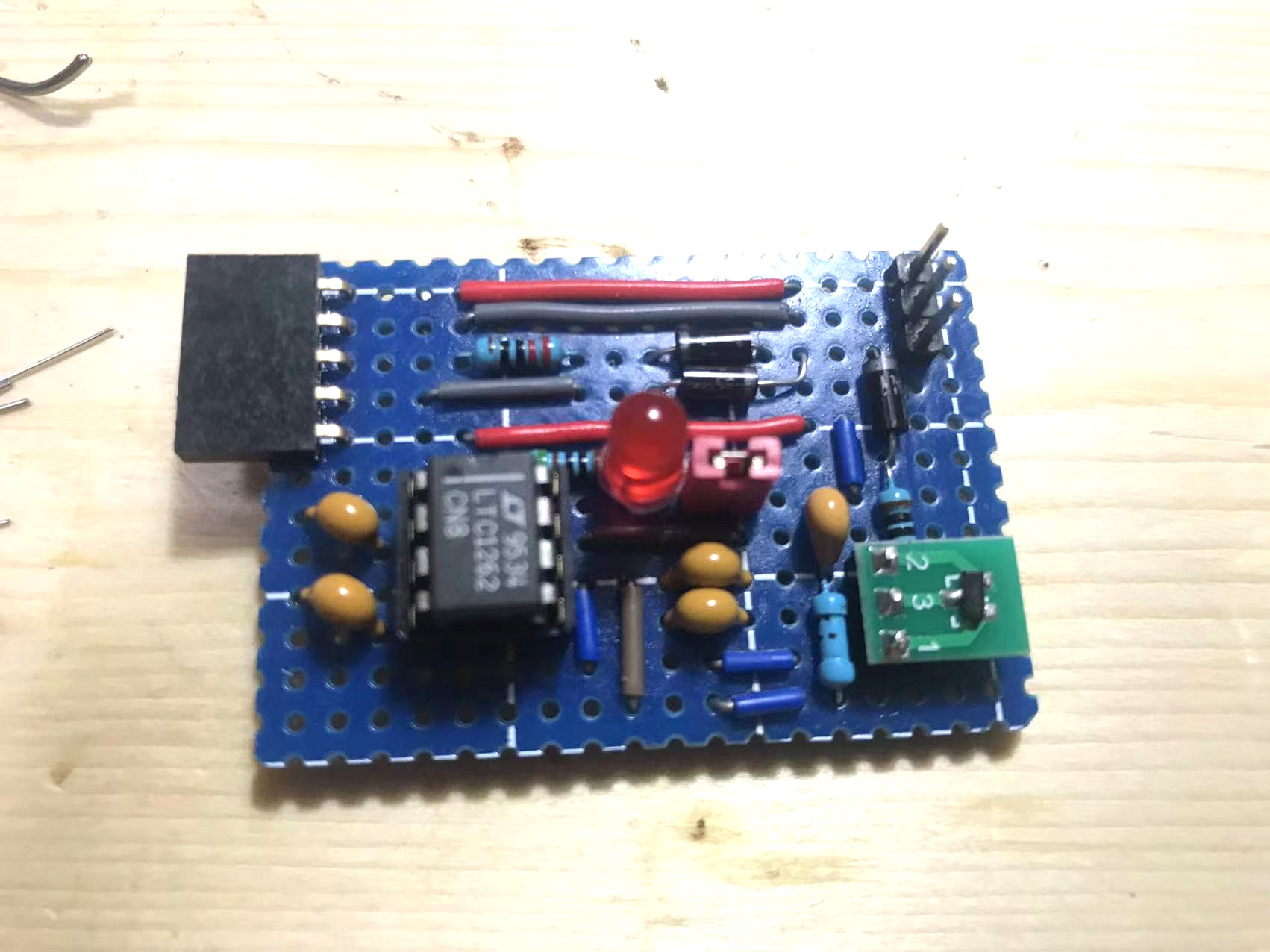
Female header(connect to a serial adapter, from top to bottom):
- VCC
- GND
- TX
- RX
- RTS
Pin header(connect to target, from top to bottom):
- VCC
- GND
- UPDI/Debugwire
There is a Jumper to control enable HV or not, closing the jumper will enable HV UPDI and turn on the HV led indicator , and open the jumper will disable HV to use the adapter as normal UPDI/DebugWire adapter.
This adapter does not require any code changes to UPDI utilies such as pyupdi, pymcuprog, etc.
Wire up your devices as below:
+--------------+      +--------------+       +----------------+                 +-----------+
|              |      |              |  VCC  |                |  VCC            |           |
|              |      |              +-------+                +-----------------+           |
|              |      |              |  GND  |                |  GND            |           |
|      PC      |      |    CH34x     +-------+    HV Serial   +-----------------+  Target   |
|    (pyupdi   | USB  |  USB2Serial  |  TX   |  UPDI Adapter  |  UPDI/DebugWire | AVR Board |
|  pymcuprog)  +------+   Adapter    +-------+     Board      +-----------------+           |
|              |      |              |  RX   |                |                 |           |
|              |      |              +-------+  (jumper to    |                 |           |
|              |      |              |  RTS  |    toggle HV)  |                 |           |
|              |      |              +-------+                |                 |           |
|              |      |              |       |                |                 |           |
+--------------+      +--------------+       +----------------+                 +-----------+
And use attiny816 as example:
Read FUSE:
pyupdi -d attiny816 -c /dev/ttyUSB0 -fr
Set UPDI pin as GPIO:
pyupdi -d attiny816 -c /dev/ttyUSB0 -fs "5:0xc0"
Set UPDI pin as RESET:
pyupdi -d attiny816 -c /dev/ttyUSB0 -fs "5:0xc8"
Set UPDI pin as UPDI:
pyupdi -d attiny816 -c /dev/ttyUSB0 -fs "5:0xc4"
Program (with any value of RSTPINCFG):
pyupdi -d attiny816 -c /dev/ttyUSB0 -e -b 115200 -f filename.hex