AMPi is an audio receiver that integrates an amplifier with a mains electricity power supply, a 4-channel audio relay switcher, a ground loop isolator, a Raspberry Pi with a DAC-HAT, a ST7735-based TFT-display, and an Arduino Nano micro-controller.
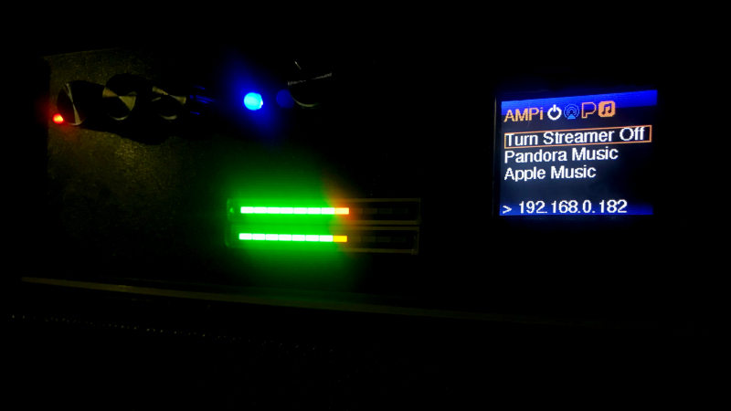
It is an integrated audio system that combines 3 external analog stereo inputs and digital-to-analog converter that supports high-quality audio playback though wireless or wired local area network audio streaming (like AirPlay), and internet audio streaming (like Pandora.com), and personal area networks (Bluetooth 4.2) in one box less than 10 inches (250mm) wide, 4 inches (80mm) high, and 8 inches (190mm) deep.
This repository is the code for the Arduino Nano. For the software and code running on the Raspberry Pi, go to the AMPi-Service repository.
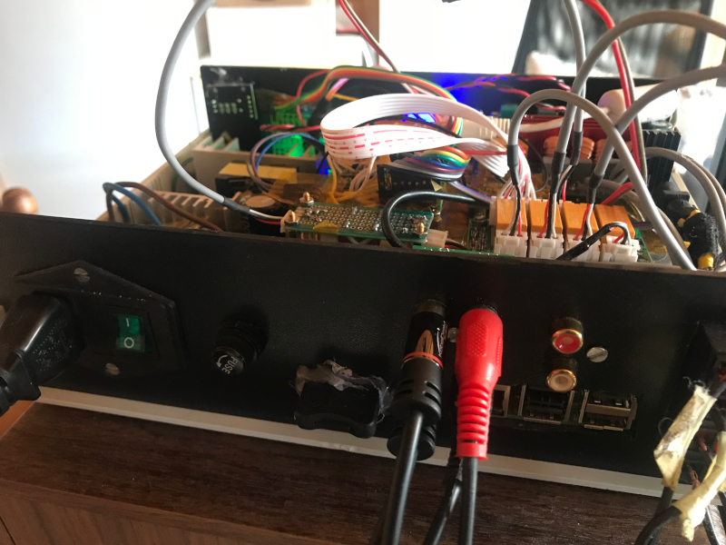
First prototype (WIP) with Raspberry Pi Model 3 and an Arduino Nano
- Mini size 250mm x 190mm x 80mm. Maxi sound
- 2 channels x 100W (Stereo) Class D Audio Amplifier
- Built-in internet audio streaming device with high-quality Digital-to-Analog Converter (DAC), e.g. 192KHz/24-bit FLAC
- Built-in pre-amplifier
- Input audio transformers functioning as a ground loop isolator. This allows for a full galvanic separation between external audio equipment and the DAC, and the amplifier section
- Computer-controlled interface that controls the screen, manages the power of and the services running on the built-in audio streaming device
- 3 switchable external analog audio input channels using a relay array through a rotary switch
- Audio level indicator
- Built-in mains power supply (100-230V)
- AirPlay playback using Shairport Sync. AMPi identifies itself as a AirPlay network player, where your iPhone or iTunes on a Mac can be connected to, to play music. You can also use iTunes on Windows 10 to play music through AirPlay or route your audio to AMPi using TuneBlade
- Bluetooth 4.2 Playback, this overrides everything and directly accessible after power-up
- Quiet & high-quality upsampled to 192kHz/16bit Audio CD playback through generic USB CD/DVD drive (WIP). Breaths new life into the Audio CD format!
- Pandora.com music player (WIP), using Pianobar
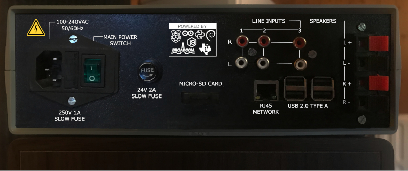
Front and back panel design (available in the .xcf and .docx documents):
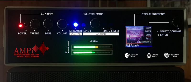
- Front & Back Panel Label - with level indicators and indications what the knobs do
- HDMI break-out cable to add in the back, needed for possibly external display or video streaming (currently shipping)
- Raspberry Pi Software - further integration with the display interface component
- Interface to enter Wi-Fi / LAN settings
- Streaming software for Apple Music
- Add CD Player interface for external USB drive
- ...and more
Use a 3.3V/5V level shifter! - as this Arduino Nano runs on 5V, while the display & Raspberry Pi require both 3.3V
| Display (Pin) | Arduino Nano |
|---|---|
| GND (1) | GND |
| VCC (2) | 3.3V |
| SCK (3) | D13 |
| SDA (4) | D11 |
| RES (5) | RST |
| RS (6) | D9 (DC) |
| CS (7) | D10 |
| LEDA (8) | 3.3V |
| Other | Arduino Nano |
|---|---|
| Raspberry Pi Power Relay Signal | D8 |
| Rotary Encoder Clock | D2 |
| Rotary Encoder Data | D3 |
| Rotary Encoder Switch | D4 |
mains --- power supply +--- 24V --- DC/DC Converter +--- 12V --- Audio level indicator
                       |                            |
                       |                            +--- 12V --- DC/DC Converter +--- 5V --- Audio Relayboard --- 5V --- Audio Switch
                       |                                                         |
                       |                                                         +--- 5V --- Arduino Nano +--- 3.3V --- Display
                       |                                                         |                        |
                       |                                                         |                        +--- 3.3V --- Serial
                       |                                                         +--- 5V --- Power Relay for Raspberry Pi
                       |
                       +--- 24V --- open/closed Power Relay for Raspberry PI --- 24V --- USB Charger --- 5V --- Raspberry Pi -- 5V +--- DAC
                       |                                                                                                           |
                       |                                                                                                           +--- USB --- CD/DVD/Blu-ray drive
                       |
                       +--- 24V --- AMP Board
DAC --------+--- Audio Relayboard --- Audio Transformer Board ---+--  Bluetooth Relay (AMP Board) ---+--- Pre-Amp (AMP Board) --- Amplifier (AMP Board) -- Speakers
            |                                                    |                                   |
Analog 1 ---+                      Bluetooth Chip (AMP Board) ---+                                   +--- Audio level indicator
            |
Analog 2 ---+
            |
Analog 3 ---+
- Arduino IDE - to program the Arduino Nano
- image2cpp - tool to create icons on the display
Tools > Board > Arduino NANO
Tools > Processor > ATmega328P (Old Bootloader)
Serial Monitor > 9600 baud
These libraries were installed through Arduino IDE's Tools > Manage Libraries... menu:
- Douk Audio / Nobsound Bluetooth 4.2 TPA3116 Mini Digital Power Amplifier Board 100W*2 (link 2) - this board uses 2 TPA3116 chips one for each channel, hence it's more powerful. It also implements two NE5532 Opamps as pre-amplifiers.
- AZ-Delivery 1.77 inch SPI TFT display and 128x160 pixels for Arduino
- Audio Relay Switcher, modified to accept 5V - essentially did not implement the voltage regulator as the LEDs & relays need 5V
- Raspberry Pi, we used a Model 3
- Nickel Alloy Audio Transformers 600:600 Ohm - We needed two; one for each audio channel
- 24 LED Stereo VU Meter
- 3.3V/5V level-shifter to protect the Raspberry Pi & Display - We needed two
- DC/DC Downward Converter 3.0-40 V to 1.5-35 V Power Supply Down Control Module, We used 2 - one for the VU meter requiring 12V, second one brings the voltage down to 5V for the Arduino powering the display as well
- AZ-Delivery Arduino Nano
- Thick Micro USB Cable to power the Raspberry PI 3
- Micro SD Card extension cable
- 24V USB Car Charger - to power the Raspberry PI, we cannibalized the one that came with a PSVITA
- 3mm thick aluminum plate to cut to size
- 100-240V Switching Power Supply 24V
- KY-019 5V One 1 Channel Relay Module Board Shield For PIC AVR DSP ARM Arduino - to control power to the USB Car Charger power the Raspberry Pi
- Speaker Terminals
- Electric (braided) wire to connect speaker terminals and mains electricity
- Prototype boards to attach components (Arduino Nano & Audio Transformers & connectors to the display and Raspberry Pi)
- Wires
- Knobs
- Kuman PIFI Digi DAC+ HiFi DAC Audio Sound Card Module I2S Interface for Raspberry Pi 3
- Fuse holder
- Fuses to protect 24V circuit
- Mains electricity switch & female connector & fuse holder in one
- Rotary Encoder Module
- DuPont jumper wires and headers acting as connectors to wire everything up
- Spacer screws to attach the Arduino and top plate where the amplifier board rests
- Velleman Case WCAH2507 INSTRUMENT CASE - GREY 250 x 190 x 80mm
- Fabric Adhesive Tape
- Kapton Tape
- Hot glue (sorry, not sorry) to hold the VU-meter and Micro-SD Card Holder strongly in place, later rework required
- Speakers - we used a pair of repaired German 3-way HECO/Summit/Hans G. Hennel speakers marked "Hifi-Stereo-Box LX90" from the 70's or early 80's (SUMMIT brand is on the crossover print only, no external brand name is left) with these specifications: "60/90W 22..20000Hz 4 Ohm"
- Soldering iron & Solder
- Rotary tool to cut & drill holes in the aluminium plates, back and front panel
- Wire Cutters
In German
LEDA kann auch an 5V doch dann wird das Display sehr schnell sehr heiß - was ich nicht für optimal halte.
Beim Betrieb mit 3.3V ist das Display nur minimal dunkler und bleibt kalt.
Die tft Funktionen kommen aus der Adafruit Grafik-Bibliothek (Adafruit_GFX) die möglichen Funktionen finden sich unter:
https://learn.adafruit.com/adafruit-gfx-graphics-library?view=all
https://cdn-learn.adafruit.com/downloads/pdf/adafruit-gfx-graphics-library.pdf

ST7735-Chip initialisieren (INITR_BLACKTAB)
Muss bei AZ-Delivery 1.77'' 160x128px RGB TFT INITR_GREENTAB sein ansonsten Pixelfehler rechts und unten.
Hinweis: https://github.com/adafruit/Adafruit-ST7735-Library/blob/master/examples/soft_spitftbitmap/soft_spitftbitmap.ino#L52
Zeile 52-65