The BeagleLogic Cape
With this cape BeagleLogic can be used to debug logic circuits upto 5V safely, so now you can debug all those Arduino circuits as well :) .
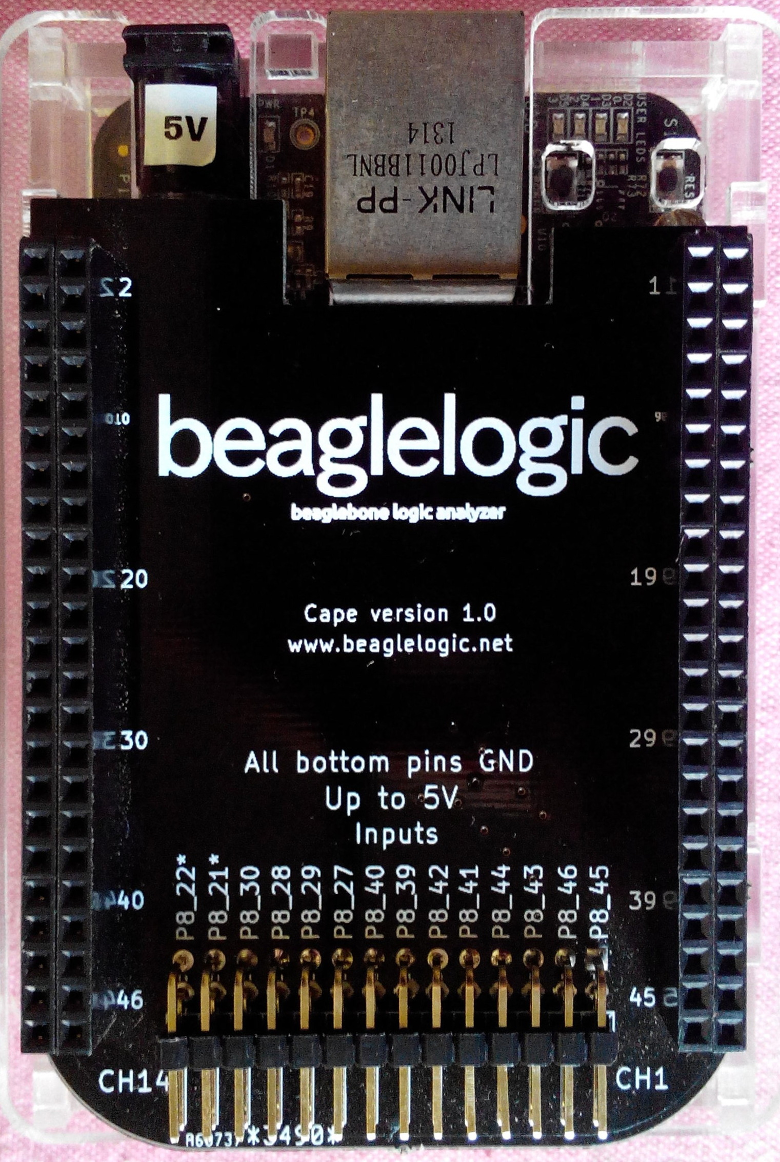
Click for the hi-res version:

The cape essentially consists of a TI 74LVCH16T245 16-bit buffer and associated power-on circuitry that ensures that the buffer does not come in the way of the power-up sequence of the BeagleBone (since the AM335x boot pins are shared with the BeagleLogic inputs). There is also a provision for cape EEPROM support that will be coming up shortly.
There are two rows of pins - the upper one is the actual signal input and just below that is an entire row of GND pins. Each pin has its ID printed beside it for easy usage.
As a value-add feature the BeagleBone expansion headers P8 and P9 are indexed after every 10 pins.
Read more about the cape design notes and the assembly and testing of the first prototype.
You can browse the cape/ folder for the KiCAD design. Gerbers have not yet been uploaded, if requested I will make them available as well.