[2.0.x] 6th-order jerk-controlled motion planning in real-time for AVR#10373
[2.0.x] 6th-order jerk-controlled motion planning in real-time for AVR#10373thinkyhead merged 4 commits intoMarlinFirmware:bugfix-2.0.xfrom ejtagle:bugfix-2.0.x
Conversation
…ion planner for AVR
|
I'll test this as soon as I get home. This is extremely exciting to me! |
|
400 cycles extra per trapezoid, and then 150 on the ISR per step. But the old code is not run, so a part of it should be compensated. The only way to know is to test it |
|
Congratulations it works! Granted I was only able to tram the axis around a bit. My temp probe is currently jacked so I can't print anything until I fix that. I suppose I could come up with a motion only gcode file. |
|
Well it seems to print and no horrible noises yet. I have it running on a couple of machines right now. It does seem to have noticeably less ringing in the print. |
|
This is really some amazing work, thank you so much @ejtagle! |
|
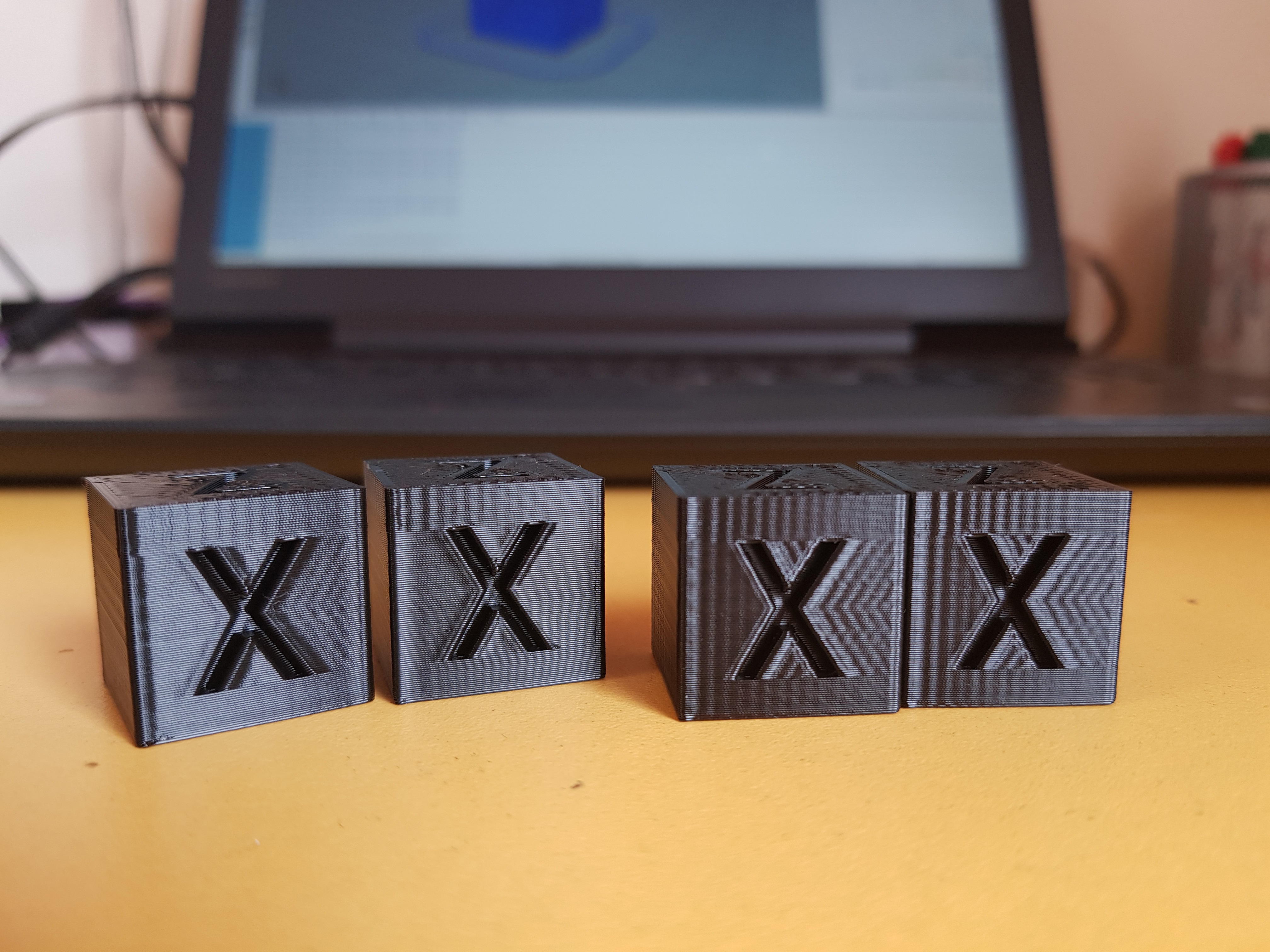
Okay, as I said on #10337 (comment) on the pull for jerk control for 32 bit, I ran some tests with this feature enabled and disabled and here are the results. I tried to angle the light so that it looks like it looks IRL. Pinging @ejtagle . Don't forget to zoom in, since pixels make moire patterns with the layers when the image is smaller. I have a Tevo Tornado, basically a CR10 clone with a 370*310 glass bed+heater, so a very heavy bed. Only mod is TMC2100 drivers. For reference, Creality ships CR10s with 500 acceleration by default, not sure on jerk. For this tests, I sliced on Slic3r PE with 2 perimeters, 10% rectilinear infill, all perimeter speeds at 35 mm/s and infill at 55 mm/s. XY jerk is 7, where applicable. Max XY accel was 3000 for the 700 tests and 5000 for the 1500 tests, once I realized that accelerations in the middle of the curve are higher. If you believe that that limit is too low and might have limited something, let me know and I'll redo some tests. The cubes, respectively, are: Acceleration- 700 700 1500 1500 mm/s^2
As you can see on the first two cubes with 700 accel, there was noticeable improvement. There was very faint ringing after the X and now is completely gone, and the more noticeable ringing on the Y is a little less visible, so an overall improvement. The ringing above the X happens because the seam is in that corner, for some reason seams produce big ringing. This has always been like that, though. In the photo it looks like this seam ringing is more pronounced on the jerk control cube, but irl they look exactly the same. Also print time decreased slightly so win-win. With 1500 accel, there was not so much luck, both cubes look exactly the same IRL and took a couple seconds longer. This is no magic fix for ringy printers, so the youtube videos with beer glasses are a bit misleading. The only thing I did to my config files, besides the usual printer stuff, was uncommenting BEZIER_JERK_CONTROL under jerk settings, so if theres something else to be done, please let me know. |

|
Your results, even if somehow surprising at first sight, once you start thinking about them, makes sense. Let me explain: The problem is not the math itself (that i do believe is bright and sound). The problem is reality and several limitations of drivers and motors and AVR microcontrollers, that start to tamper the calculations. The first problem we may have if positional inaccuracy of stepper motors (i hear... What??) ... And let me explain: Depending on drivers, stepper motors do not have the exact same deflection for each microstep, and definitively the torque of a motor depends on microstep position. So when you start moving faster and faster, you have less and less torque available, and less torque means less control of the exact position of a given stepper motor (https://hackaday.com/2016/08/29/how-accurate-is-microstepping-really/). Inaccuracies in position and torque can be seen as perturbations that trigger themselves resonances of the system. The second problem is Marlin and AVR: We are sure that we need exact timing of pulses to the drivers, so movements are smooth. But, AVR has an unknown time-positional latency (to define it properly, the time from where a step pulse should be produced, and the actual time where the pulse is produced of about 0 to 2uS ... Lets do some math: If going at 50mm/S, and assuming 80 pulses per mm, then the amount of required pulses per second is 4000 pulses per second, or one pulse every 250uS. So Marlin, due to the way pulses are generated, is incurring a 2/250 = 0.8% positional error. And probably the 3rd problem is voltage being used to drive the drivers. The faster the drivers switch coils of the stepper motor, due to coil inductance, they need higher voltages to be able to get maximum torque of the motor. With 12 volts, it is very hard to get maximum torque at high speeds. What essentially i say is the faster the motor goes, the less torque, and less reliability of the position, and less reliable position and less torque means less control of position, and less control of position means more vibrations that can´t be controlled or dampened. I'd expect a 32bit controller would improve timing, and also, powering from higher voltages would restore torque at high speeds. And obviously, the choice of drivers also is important. As you say, there is no magic, but improving electronics certainly can help :) |
|
@ejtagle from what I've read you don't modify how the trapezoid is generated, so the normal Marlin jerk settings are still in effect causing instantaneous velocity changes? |
|
I see! Very insightful reading, thanks! That hackaday article is very interesting. I wish they would have tested more drivers though, such as the TMCs I'm using. The 256 uStep interpolation and funny control techniques they use might have interesting consequences on positional accuracy and smoothness. I'm thinking on getting some 2208 drivers, since they allow more current and torque before overheating. Also, motor's quality should play a significant part on this too I guess, but after searching a little on google I can't really find any info on stepper motor quality. Are all steppers equal? Or at least perform good enough not to be significant? The whole machine runs on 24 v, so I believe I can't improve that by much. Perimeters were made at 35 mm/s, so following the same calculation you made, 35*80 (which are actually my steps/mm) = 2800 pps, so one step every 357 us. Positional error over time is then 2/357 = 0.56%. Doesn't seem much to me but perhaps it's significative for following very precisely the bezier acceleration curve. Do you think that it would be significant improvement going 32 bits in this specific case? I know it's better all around for different reasons, but do you believe this sub 0.6% error could affect vibrations in a very significant way? Also another question, how do you think the linear advance 1.5 implementation would play with this? I believe it assumes the normal trapezoidal acceleration, but given the nature of bowden tubes and molten plastic perhaps it's not that bad. And more importantly, processing power! Perhaps AVR can't handle both. I checked your assembly code and it's brilliantly optimized (not that I could follow it much, but I read your posts) and maybe both features are too much to handle. |
|
Yes, using 24v will get the best from any driver. In fact, i am thinking in implementing a linear-advance 2.0... ;) - The idea is not as complex as it seems:
Look at pressure advance at https://github.com/KevinOConnor/klipper/blob/master/docs/Kinematics.md I am a little short on available time right now, so it will take some time to modify the linadvance 1.5, but probably i eventually will Motor quality probably plays a role, but not too much. There are 2 coils with a 90 degrees separation. That is not a complex thing to achieve in manufacturing process |
I thought so, I'm going to say that this is going to a huge factor in the ringing you are seeing @Itox001, Marlins jerk setting (actually maximum instantaneous velocity change) is a necessary evil for synchronous movement at reasonable speeds but it is the antithesis to this PR, |
|
Perhaps I'll do some tests again with 10000 max XY acceleration, just to see what happens. Excellent! If I can do anything to help you, let me know. I've been after linear advance for ages, but 1.0 didn't work at all with bowden and 1.5, even though I could get it working and seems to help most of the time, has it's random quirks which make it not 100% reliable in all cases. So, what would you suggest? Higher acceleration and lower jerk? Or viceversa? Or just modifiy jerk? Or perhaps all of them and document the results. I would love to, but I'm somewhat short on time too so if you had a lead it would be cool. What I don't really understand is why is jerk still used? Isn't the point of jerk control to take jerk continuously from 0 through the acceleration and then at 0 again? Where would the jerk defined in Marlin enter here? |
|
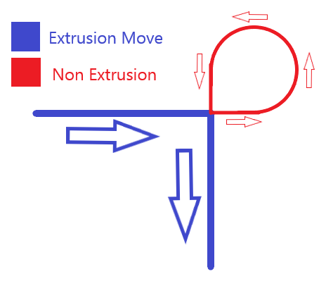
I asked myself the same question about Jerk. Imagine the nozzle going along the X axis, and then doing a cornering and going along the Y axis. |
|
Thanks for the explanation, I now see it clearly. That GRBL method actually looks quite optimized, it would be awesome to have it on Marlin. Specially because lowering jerk and cranking up acceleration is just a patch to achieve less ringing while keeping total print time the same, but corners will still be done in a slow way, which brings more undesirable effects, such as bulging on sharp turns because of pressure lag on the extruder (which the cubes on the above photos present heavily). Of course, less ringing in the same print time is still welcome, but if the corners are made too slow and they bulge too much, it may be more undesirable than ringing. To solve this without the faster corners that an improved algorithm could give, then there will only be two solutions, either lowering the overall speed, or having pressure control that can compensate the pressure lag on speed changes even on bowden, as you said above. Too bad that deep time-consuming modifications are needed, but seeing how you produced some insanely complicated assembly code in a couple days, I'm hopeful 😁 I also noticed that I can not set different accelerations on X and Y, the only way to do so is limiting the axis acceleration with the X or Y maximum acceleration values, but this would interfere with the high acceleration in the middle of the bezier curve, right? Since usual printers with moving beds have very different characteristics on the X and Y axes, I believe that tuning the accelerations independently is desirable. I'm off to test jerk/acceleration values to see what it results, if corners do bulge more, if print times can be maintained and if ringing is reduced. |
|
Okay, I'm completely at loss now. So, no ringing on X at 7 jerk, just like the the second cube on my pics above. But if I lower it to 4, then I see some very faint ringing, and if set it to 1 then there will be noticeable ringing. If I raise it to 15, then heavy ringing. So it looks like jerk has a sweet spot and doesn't like being so low? I thought that when talking about vibrations, then slower was always better? |
|
Maybe some jerk values cause a resonance in your machine ? ... Jerk value gives the amount of torque jump ... That is the only thing i can think about right now... |
|
The lower the jerk setting, the slower the machine will be as it transitions around a corner. At lower speeds, the rate of pulses being sent to the motor can get very low. With some machines, this very low pulse rate excites a resonance in the machine. This was a much bigger problem years ago when microstepping was 1/8 or even 1/4. I believe that part of the original reason for the legacy jerk setting was to "jump" out of this resonant range and to a speed that machines of that time "liked" better. |
|
That makes sense. I guess that even the TMC2100's 16->256 microstep interpolation isn't enough. Perhaps true 256 microstepping can fix the issue? |
|
My anecdotal experience indicates that 32 bit controllers seem to do better with surface ringing even with no hardware changes, but that might be confirmation bias. I don't know if the higher pulse timing jitter on an AVR is a perfect explaination, but it is an easy scapegoat. Some day I will do an A/B test with the same gcode run on both an AVR and 32bit controller back to back. Unfortunately the only 32bit controller I have only runs my own firmware, so it's hard to make a perfect comparison. In CNC machines, corners are almost always rounded. If a perfectly square corner is required, the machine will come to a stop before changing direction. There is no functionality like the legacy jerk we use where the velocity instantly jumps. If you look at a HAAS machine for example: https://diy.haascnc.com/reference-docs/advances-motion-control The accuracy (or smoothness) setting is tied to motion acceleration approximately as follows: P1 - Rough = max_acceleration (There is likely more happening under the hood, but the easist observable change is the acceleration.) The corner rounding parameter (E) is (in slightly over simplified terms) the distance from the junction that the actual tool path starts to deviate from the current line segment to make a smooth transition to the next line segment. This path rounding allows heavy high momentum machines to make smooth moves without breaking the laws of physics. Default for most Haas machines from the factory is 0.025in (0.6mm), although it will not blindly follow this setting. This might be an area of exploration to reduce ringing. I'm cautiously optimistic that that small amounts of corner rounding could be used to reduce ringing with an insignificant impact on accuracy. As long as the effective path smoothing radius is less than half of the extrusion width, there will be no dimentional change in the inside of the corner of a 90 angle. There will be a slight reduction in width on the outside of the corner. Given the compliance of most 3D printers, it is quite possible that the head would swing to the outside of the theoretical path and the error would be less than expected (corner bubble/bulge would shrink on corners with continuous motion, but this would do nothing for start point corner bulges). Sorry for the rabbit trail from original post... I expect to test the AVR version of 2.0 tonight with this feature enabled. |
|
Personally, I try to design all of my parts without square corners to avoid these very issues. |
Slicer. |
|
😜 well of course you'd say that. |
|
@ejtagle @thinkyhead what happens when you switch from one positive acceleration to another positive acceleration? Say the gcode path turns 45 degrees and the X axis changes acceleration from +1400 mm/s^2 to +2000 mm/s^2 while below the velocity jump "jerk" limit so there's no corner slowdown. |
|
@rcarlyle — Is that something slicers will generate? Acceleration applies per-block, so when acceleration is changed, it alters the way that speeds are calculated starting from the next block added forward. If the next blocks include changes in speed, then the change-over-time will be calculated using the new acceleration. The effect is as one would expect. AFAIK, jerk will apply only in the case where there are changes in direction or starts-from-zero on individual axes. |
|
@thinkyhead you’re asking, will slicers generate 45 degree turns? Yes, they can generate any angle of turn at corners :-P I must not have been clear in my question. Within each gcode segment, the motion planner can do different things, depending on segment entry/exit speeds calculated by velocity jump “jerk” limits, and allowed acceleration/speed:
The motion planner can also put any two of these back to back when traversing a corner between two segments. The magnitudes of accel, decel, and coast on each motor axis can be any value less than the maximum, based on the direction of motion and how much that axis has to move to add up to the desired relative nozzle motion vector. For example, a +X motion at 0 degree heading and a +X+Y motion at 45 degree heading have different accelerations on the X axis even though they’re both accelerating on the X axis. So, my point is, it looks like y’all have tested this code with right angle turn type geometry (which will generate pretty much solely full trapezoids for each gcode segment) and it works. But what about motion geometry that transitions between different acceleration values at a corner? Does the bezier curve profile create a smooth transition from one acceleration rate to another? Or does it S-curve down to zero axis acceleration at the corner despite both the entry and exit from the corner having positive acceleration? |
I was asking if slicers include acceleration changes in the G-code to be extra clever on corners. |
Well, we test with various objects and observe the results. Some round, some pointy, etc. I'm not deeply involved in the implementation of this feature, which is still experimental, so I can only collate these observations and pass them on to those more intimate with the code to make any needed refinements. I'm sure @ejtagle can address your questions with more authority than me. |
|
@thinkyhead The only slicer I'm aware of that attempts to do acceleration in gcode is Makerware / Makerbot Desktop, which has (had?) a special mode that reduces perimeter speed (G1 feedrate) via an entry/exit speed stair-step ramp for tight arcs. But it's buggy and produces weird motion results because it conflicts with firmware acceleration, so nobody uses it. It's possible some slicer issues acceleration parameter change gcode commands instead (which would make more sense), but I'm not aware of it. Changing accel parameters by print geometry is kind of a fool's errand though... acceleration code in these GRBL-derived motion planners only triggers acceleration slowdowns at sharpish corners, and pretty much ignores finely-faceted curves because the change in velocity vector at the corner is below the "jerk" / junction deviation limit at each waypoint, even though the aggregate centripetal acceleration through multiple segments of the curve might be extremely high. All our firmware acceleration schemes already works well on sharpish corners, and doesn't work at all on smooth curves, so there's really not much usage case in the middle where reducing the acceleration parameter accomplishes much. What I'm wondering from @ejtagle is whether the bezier curve generation blends entry/exit accelerations between consecutive gcode segments (or sub-segments). If not, acceleration will drop to zero at the segment waypoints, even if acceleration is same-sign in those segments. I think you're going to get some pathological acceleration oscillation from that with delta segmentation or certain types of gentle arc geometry, most importantly if the segment rate matches a resonant frequency of the printer. |
I finaly managed to grab the latest Marlin and did some test prints with the Bezier function and also the new jerk mode (on an AVR). Awsome work! Regarding LA: Can you explain the meaning of the acceleration values with your bezier function enabled? I guess the given acceleration (like 1000mm/s²) is now the average acceleration across the interpolation? LA 1.0 would most likely play quite nice with your bezier implementation as it calculated the extruder speed within every ISR loop. If you want to try a v2.0 I would be quite happy as I'm sure you are able to do a much better version than I will ever be able to (looking at your PRs). Just note that there are a lot of hidden traps when playing with pressure advance, I created two (I call) working versions of LA but also 10 or 20x versions by try and error which looked good, but never worked for multiple reasons. If you have some questions or you need a tester for new code, I will be happy to assist you! Side question: |
|
@Sebastianv650 : LA is a very complex thing on Bezier, but mostly doable. Yes, the only way to properly perform it is to evaluate the formulas at the stepper ISR. Luckily, the formulas can be translated to a difference equation of the form advance = (acceleration[-1] - acceleration[0]) * advance factor. And the advance factor is just an 8bit multiplication. I estimate 20 cycles on AVR to compute it. Yes, on Bezier interpolation, the acceleration limit is not stricly enforced. The mean acceleration of each phase of the trapezoidal shape is less or equal to the maximum acceleration allowed for the movement. That´s the problem with Bezier: Machine resonances are less excited, so you should get less ringing. Try the ubiquitous calibration cube (that shows ringing in the lateral faces along the numbers. And increase printing speed as much as you can 👍 |
|
I tried test cubes with and without bezier again, this time at higher perimeter speed. In fact I get more pronounced ringing with bezier using the same print acceleration of 1100mm/s². Maybe due to the fact I'm using an AVR, I have no printer with 32bit board at the moment. But I can also report something good: LA does it's job also with bezier enabled. Optimization is possible, no doubt, just wanted to test if it's at least safe to use them both as they are now. |
|
@Sebastianv650 I'm not sure how much the bezier feature can help with ringing on its own when it still adheres to the jerk settings. You can try setting your jerk values very low and compensating with the much higher acceleration that should be possible because of the smooth transitions. The junction deviation feature should also help. |
|
@p3p In theory it could have an effect, as any sudden change in acceleration is a jerk. It would show up in a different kind of ringing, but that's only detail. |
|
@Sebastianv650 I made some tests, documented them on the comments above after the pics. My findings were sort of like yours, and found that lowering jerk actually produced worse ringing. I found a sweet spot at 7 jerk, any lower or higher and ringing would be more pronounced. So I'm with you, I believe somethings weird happening. |
This pull request implements the 6th 6th-order jerk-controlled motion planner for the AVR target. Lots of thought on this and several ASM routines.
I have to make a request: Please, someone test this in actual hardware! . I have an Arduino Mega2560 so i was able to execute, debug and make sure the routines return exactly the values expected for each possible argument and value, but my RAMPs board was converted a long time ago to be able plug it into an Arduino Due, so i canno´t plug it into the Mega2560. So, this code should work, but i´d like someone to try it in a real 3d printer
@thinkyhead : I was able to reduce the cycle count of the coefficient estimator even more, it takes 216 cycles to execute, and produces bit exact results (i wrote an Arduino sketch just to test all those ASM functions, and compare the values returned with generic ones written in C. There was no difference at all for all possible input values