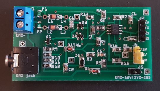
The board has the full send and receive circuit to interface between the EMS bus and a 3.3V or 5V interface logic microcontroller.
The current and all previous versions have been succesfully running on many boilers for a number of years already.
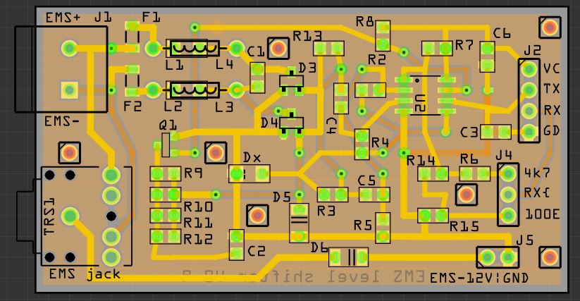
The board has the text 'EMS level shifter' on it but in fact it does more than just that.
For reading data from the bus the board removes the DC offset and converts the higher voltage EMS signalling down to TTL level.
For writing data to the bus it translates the TTL input from the microcontroller to a current instead of a voltage change.
It can be plugged in directly to the EMS service jack on the boiler or parallel to the thermostat.
It is powered via 3.3V or 5V from the microcontroller board.
Some limited protection is provided by two polyfuses to protect the EMS bus from your experimental f*ck ups.
But you can buy a version 1.0 PCB or an EMS Gateway HERE..
- The board is double sided but all components are only on the top side.
- Components are all SMD except for the connectors those are through-hole.
In theory the board could have been smaller and f.i. populated on both sides. However it was designed from a more practical point of view. It has larger SMD components and some additional room around them so the board is hand solderable for even not so skilled persons.
Furthermore the board has all components on one side so I would only need one PCB solder paste stencil if I wanted to use one. Those things are relatively expensive compared to the price of the PCB's themselves. And you can't really do two-sided reflow soldering at home anyway. - All connectors are through hole, these are usually much stronger than SMD connectors which can easily be ripped off the board if f.i. you pull too hard on an attached wire.
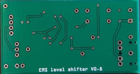
- The bottom side of the board has a ground plane for reduced noise.
- The board has several pin holes you can use for mounting. They are not attached to anything.
They are in the normal 2.54mm grid spacing so f.i. you can use a few header pins to directly solder the EMS board onto an Arduino prototyping board so it will fit neatly and sturdy on top of an Arduino. - Board size and connector positions were chosen such that it all fits on top of an Arduino prototyping board.
The last version in this format is V0.9. It has been superceded with versiion 1.0, which is compatible with the Pi HAT.
The only difference between V0.8 and V0.9 boards is the silkscreen. There were a few changes to the text on the board but the schematic and layout is identical.
V0.9: Only difference with V0.8 is the silkscreen.
V0.8: Changed the voltage selector to a resistor selector. R15 is no longer populated, changed resistor value R14 to 100 Ohm.
V0.7: Removed wire bridge from V0.6 and added a ground plane. Layout is more compact. Moved around some components. Added vias for mounting. Changed EMS 12V pin header. Added two polyfuses.
V0.6: First production version. This version has a wire bridge and no ground plane.
You can find the instruction for use as added to the shipment of the fully populated boards here.
But you can buy a PCB or an EMS Gateway HERE.