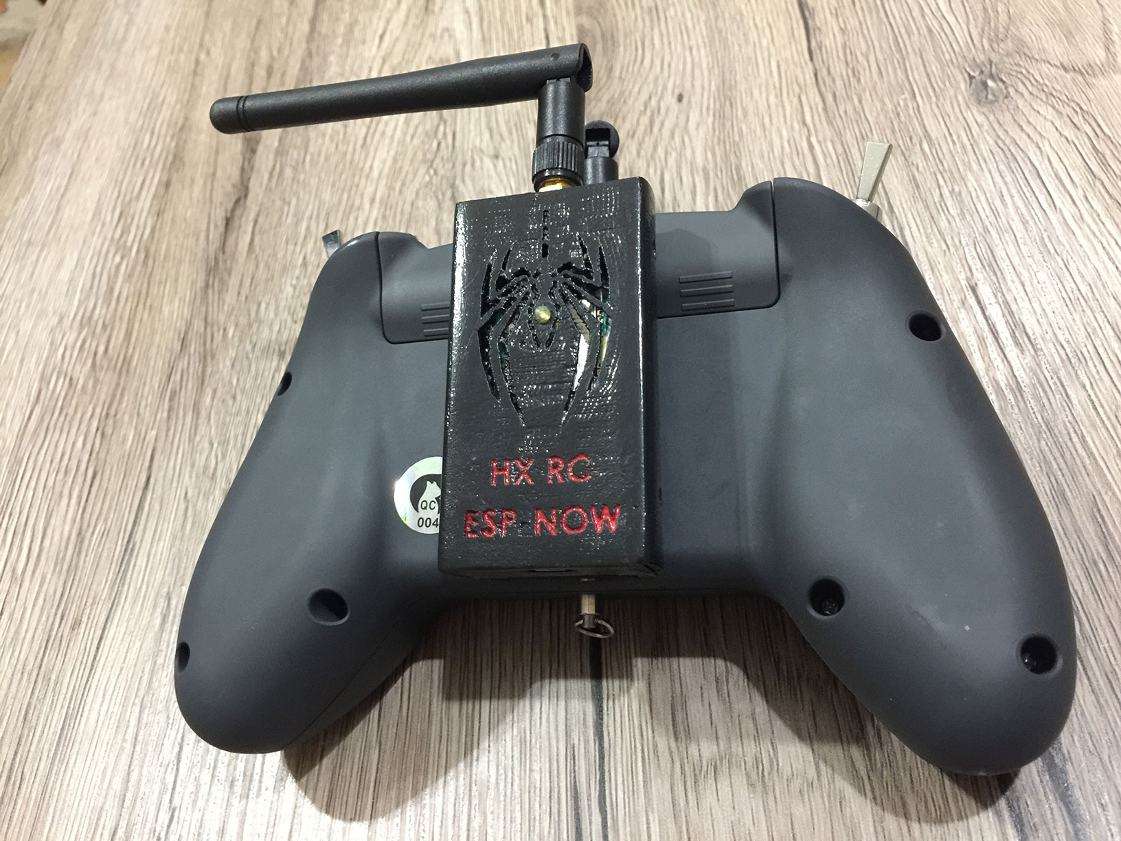
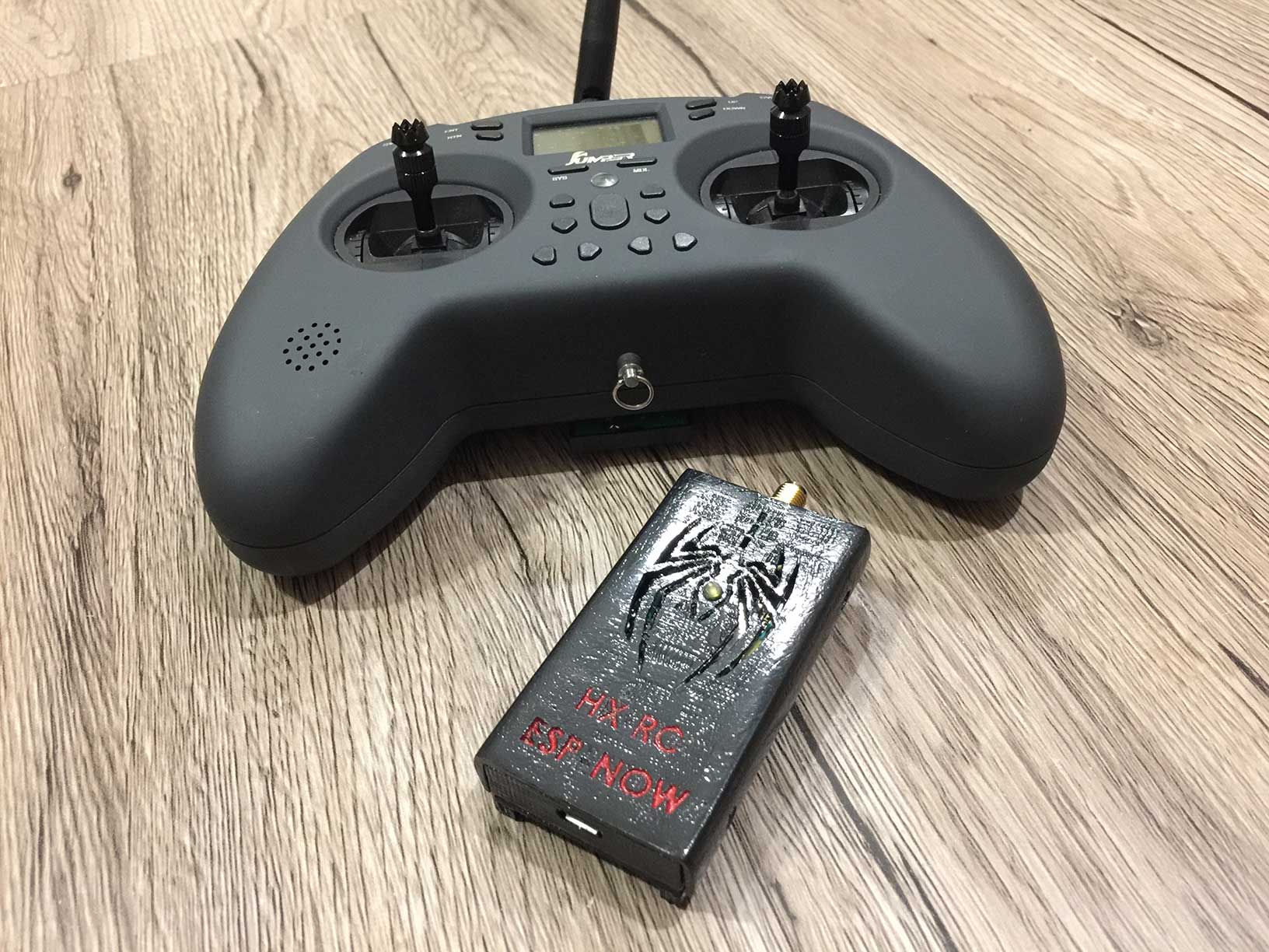
This is external transmitter module for Jumper T-Lite.
In general, can be built for any RC controller with SBUS output.
- 3D Printed parts https://www.thingiverse.com/thing:4948833
- ESP32 DevkitC U32 or ESP32 Devkit V1
- HC-06 bluetooth module
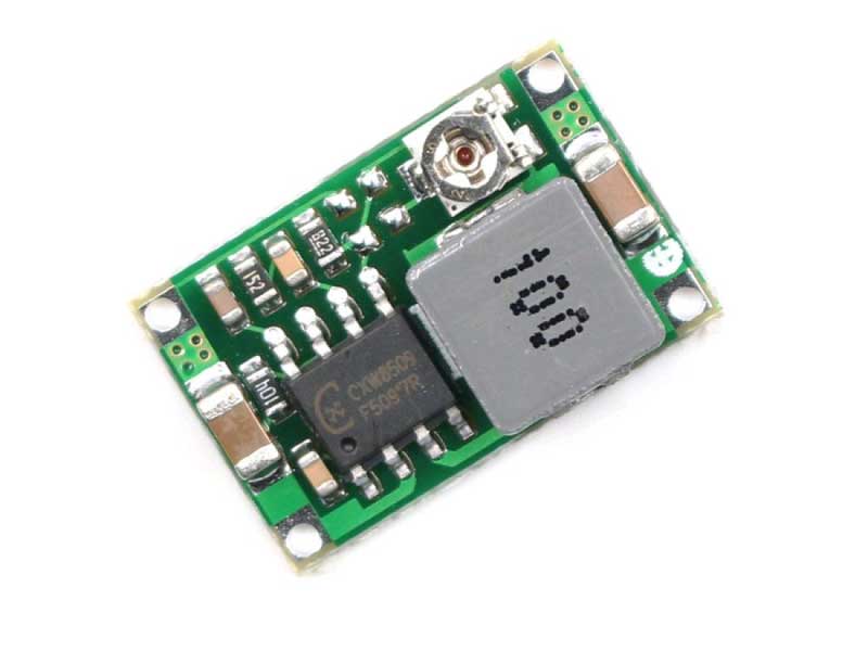
- DC-DC Mini360 module
- Resistors: 10K, 1K, 220Ohm, 100Ohm
- Schottky diode <0.4V drop voltage: 1n5817 or SS16 or other
- Yellow LED 3mm
- SMA to U.FL wire
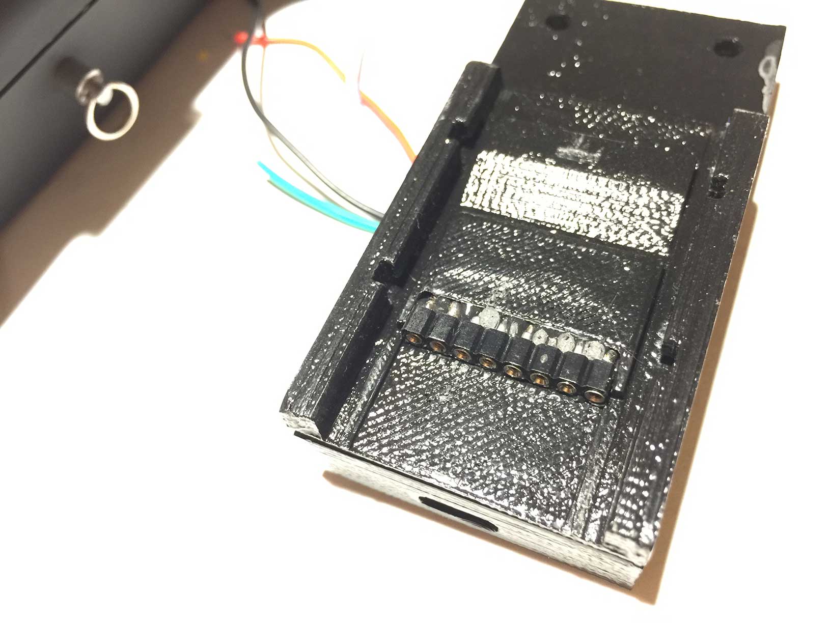
- ZL307-1X8 connector
- 4x M2.5x3 bolts
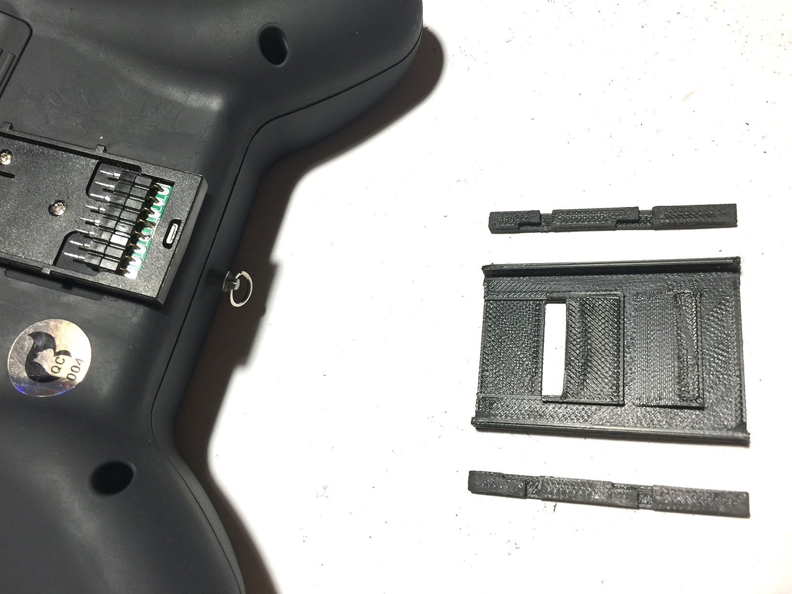
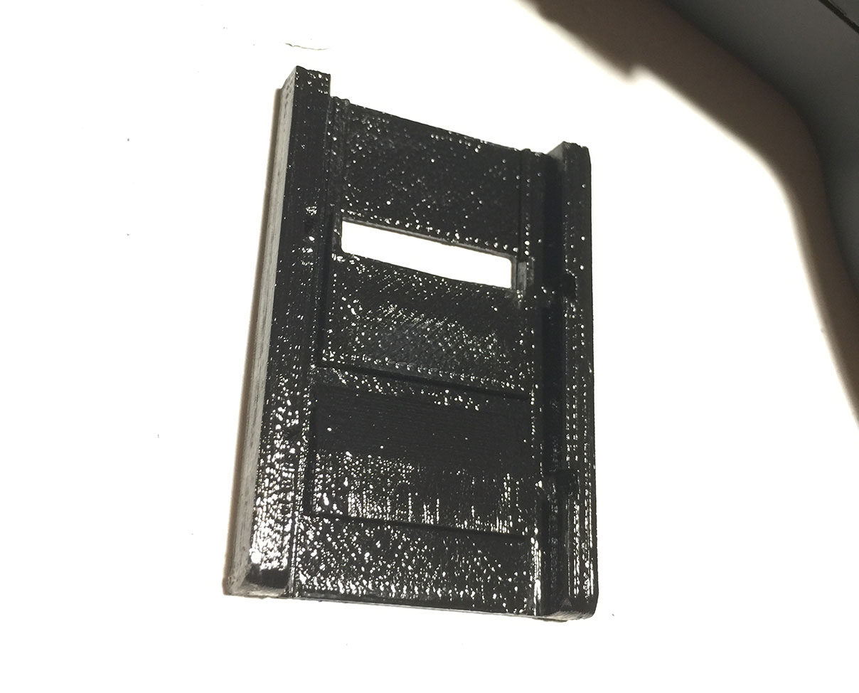
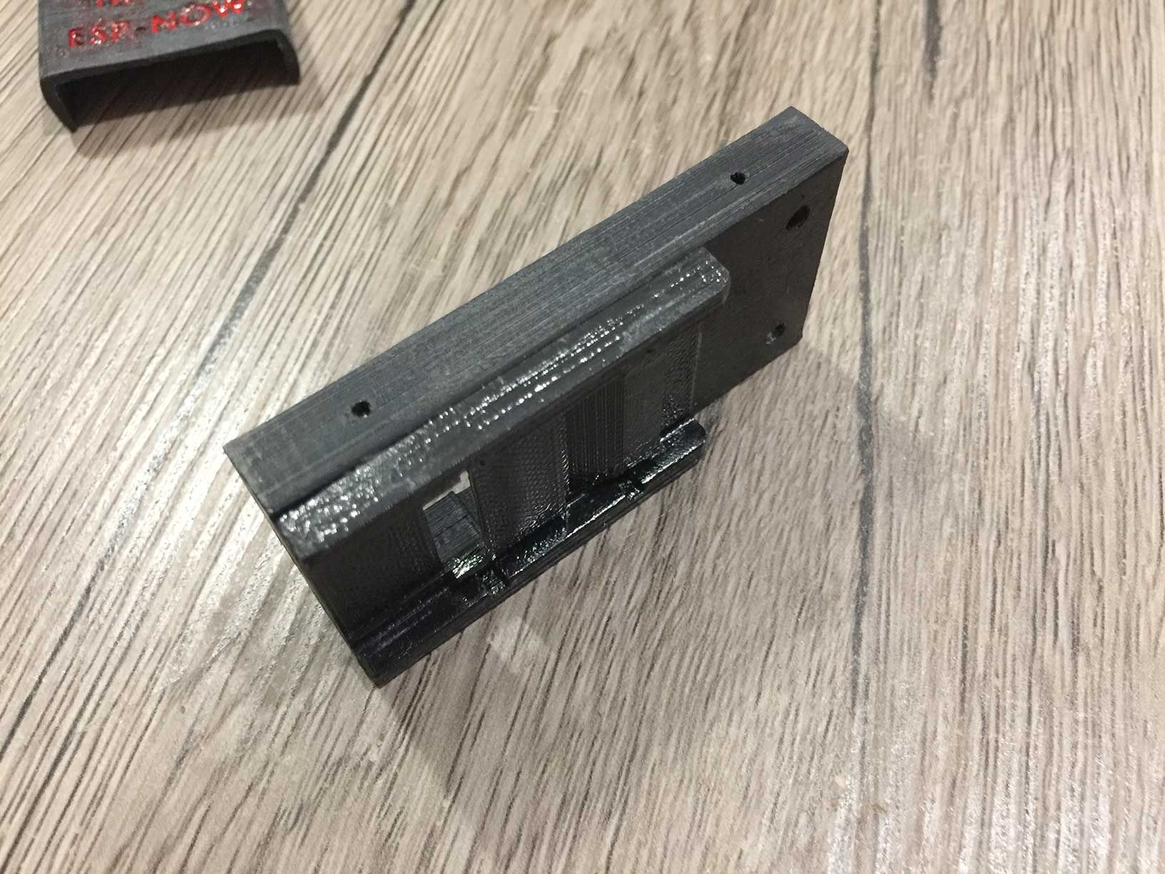
Print base and two insets:
Glue insets inside base part:
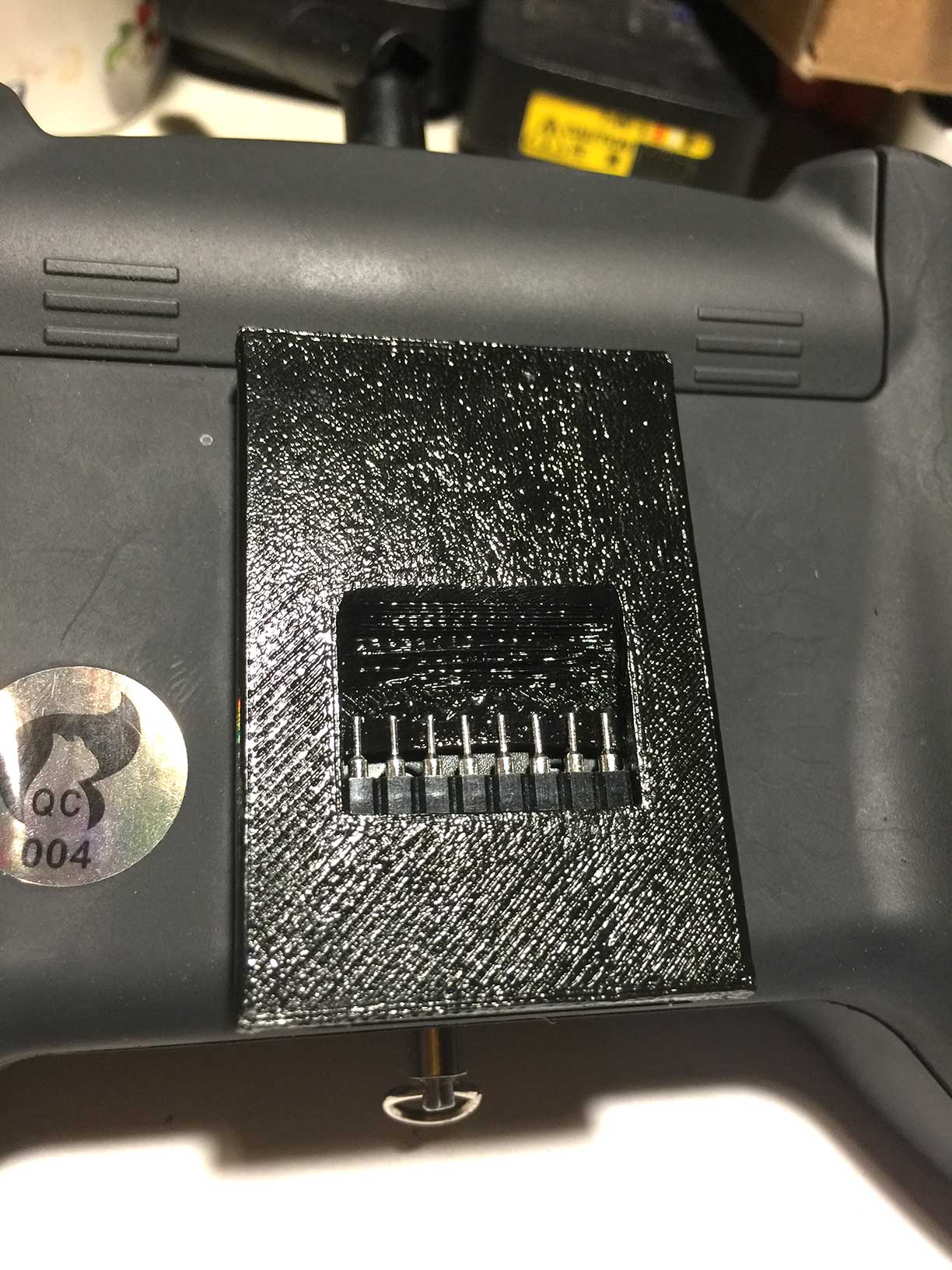
Assembly should fit External module bay with connector:
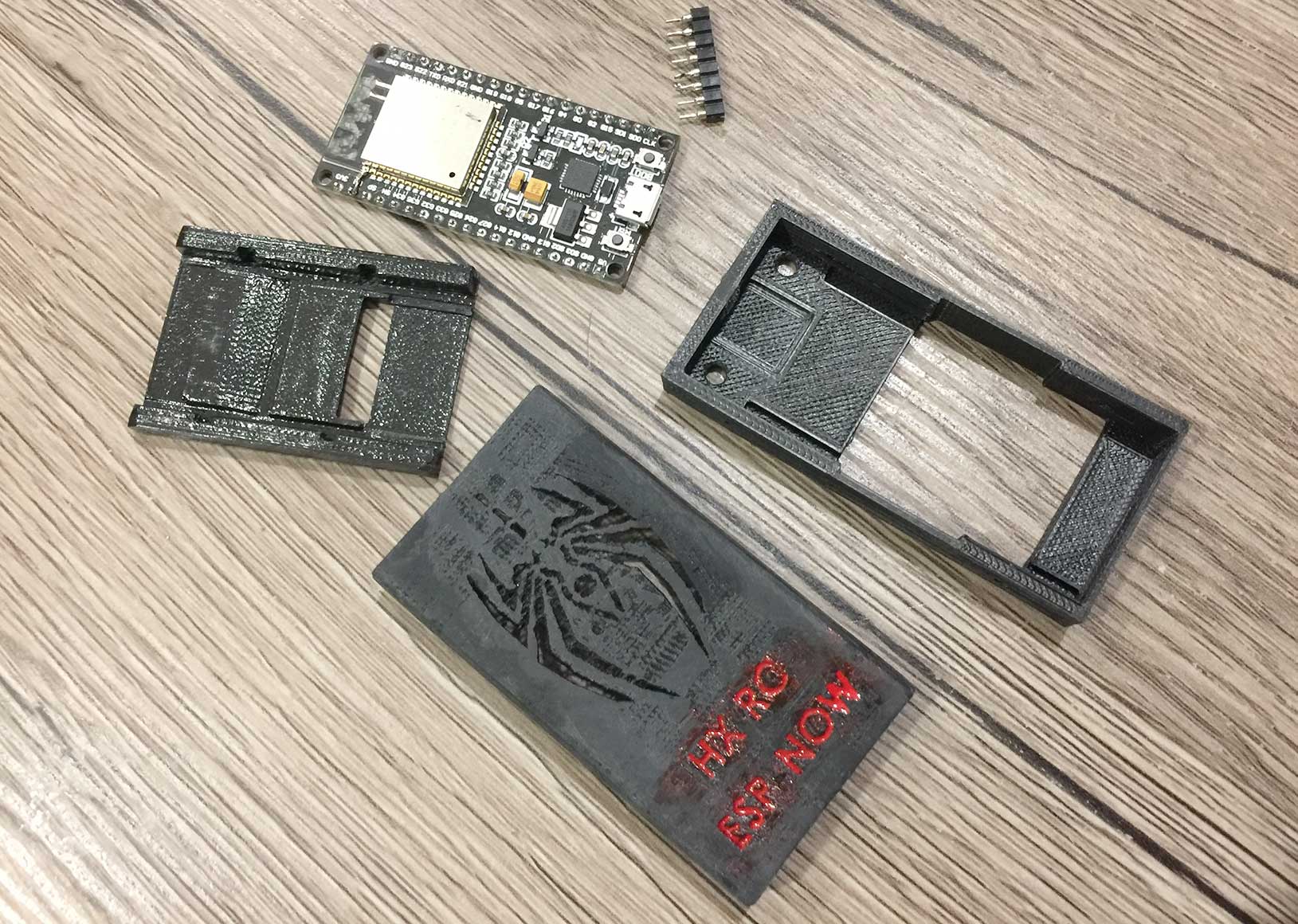
Print main part and cover. Paint letters on cover:
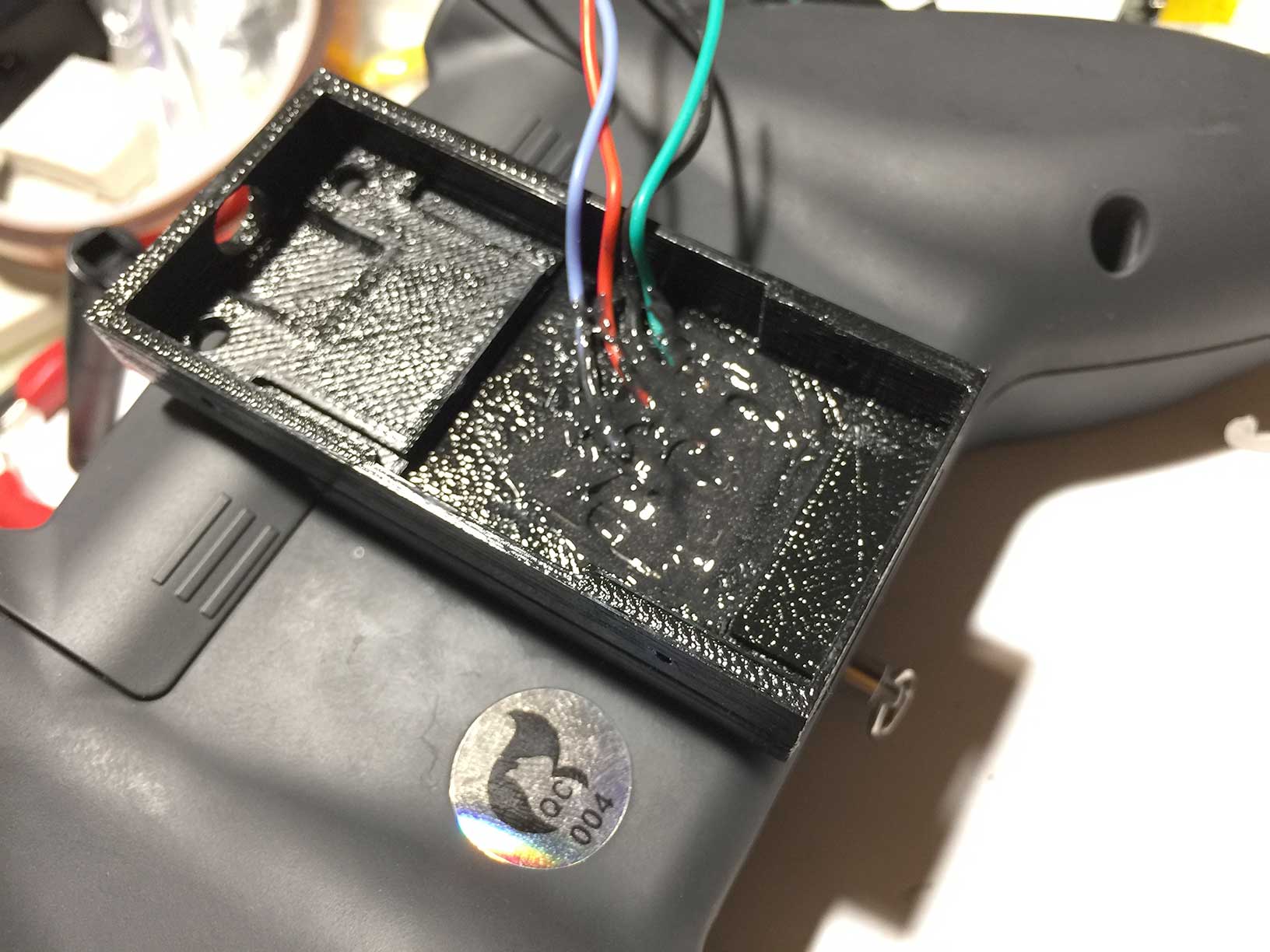
Glue main part to base:
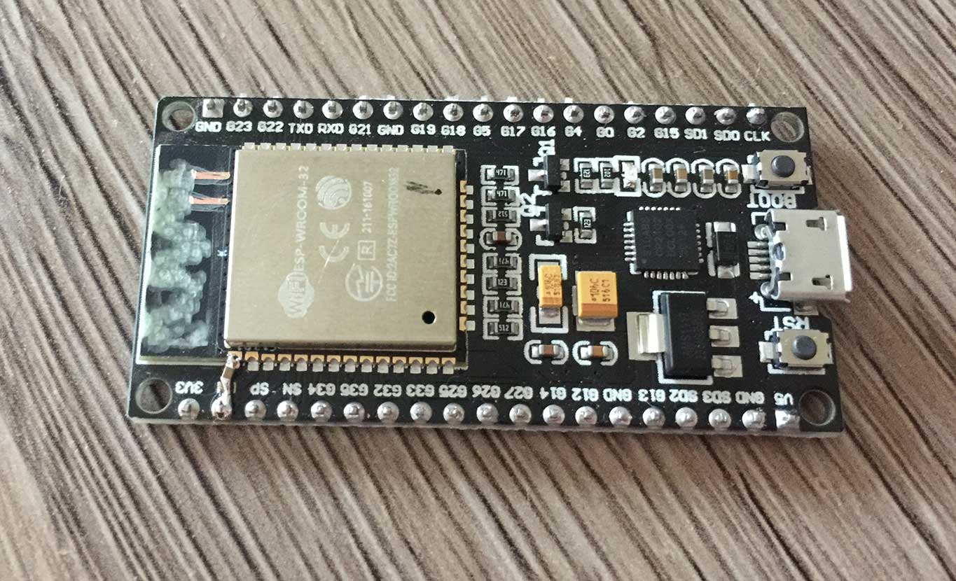
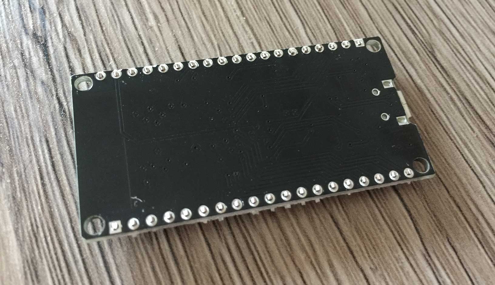
Prepare ESP32 module. If you are using module without U.FL connector, remove internal antena leaving only two pins for soldering antena extension wire.
ESP module buttons will not be accessible inside shell. Some modules from Aliexpress are known to be defective. If your ESP32 module does not enter programming mode automatically during USB programming, add 1uF capacitor between EN and GND (look at bottom left corner):
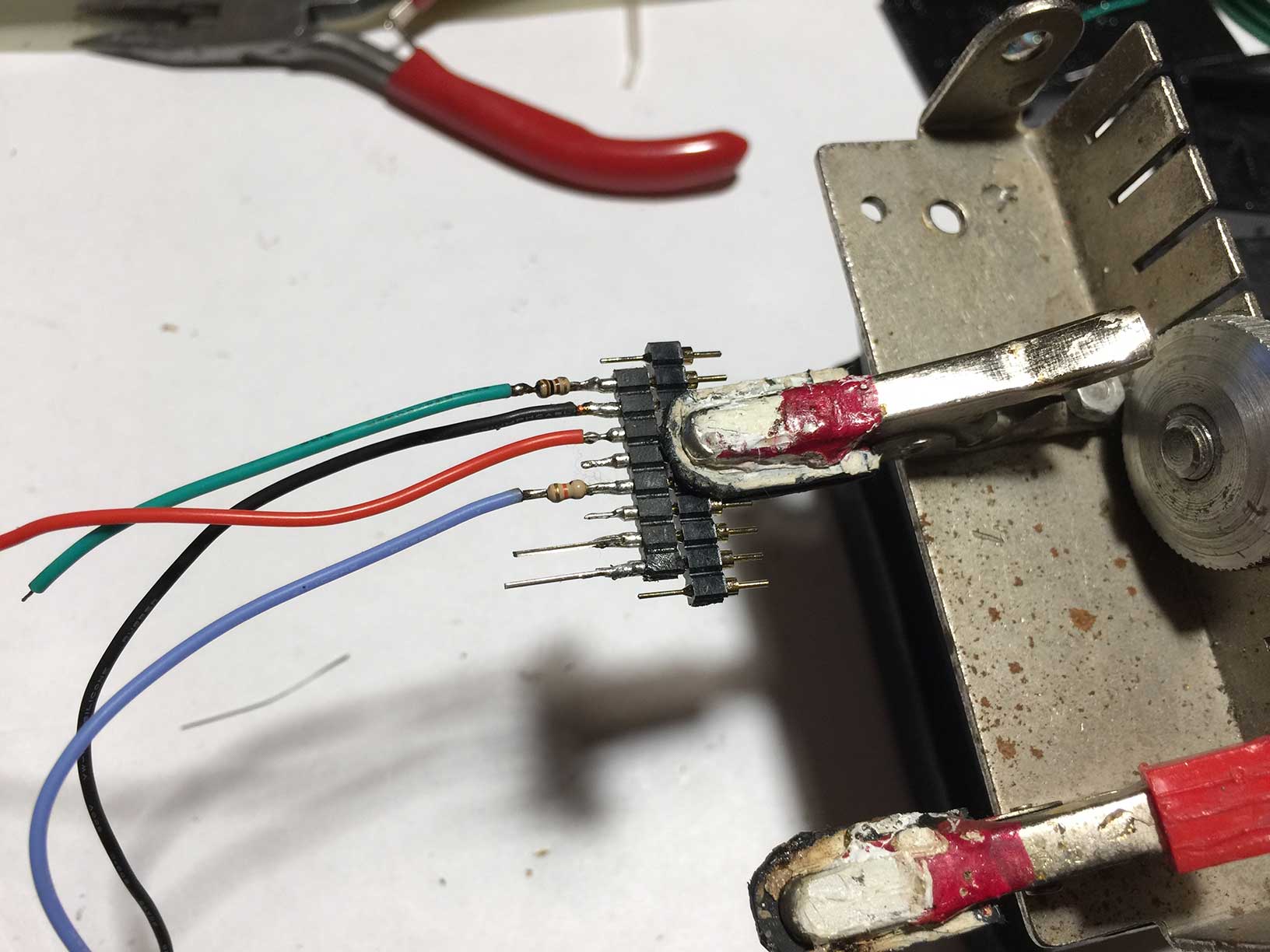
Solder resistors and wires to ZL307 connector:
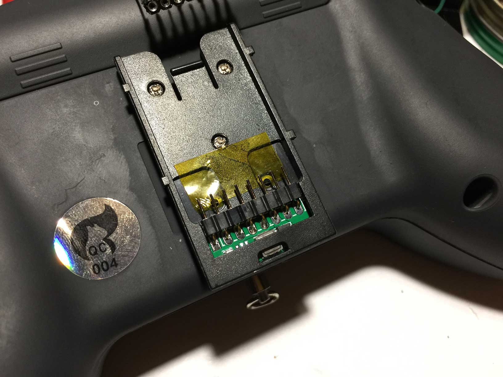
We are going to glue connector to shell inplace. Apply capton type to transmitter to avoid gluing module to transmitter:
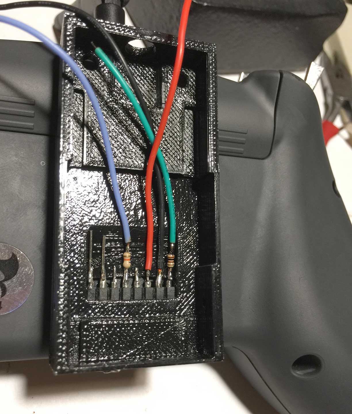
Put shell and connector to External Module bay:
Glue with epoxy:
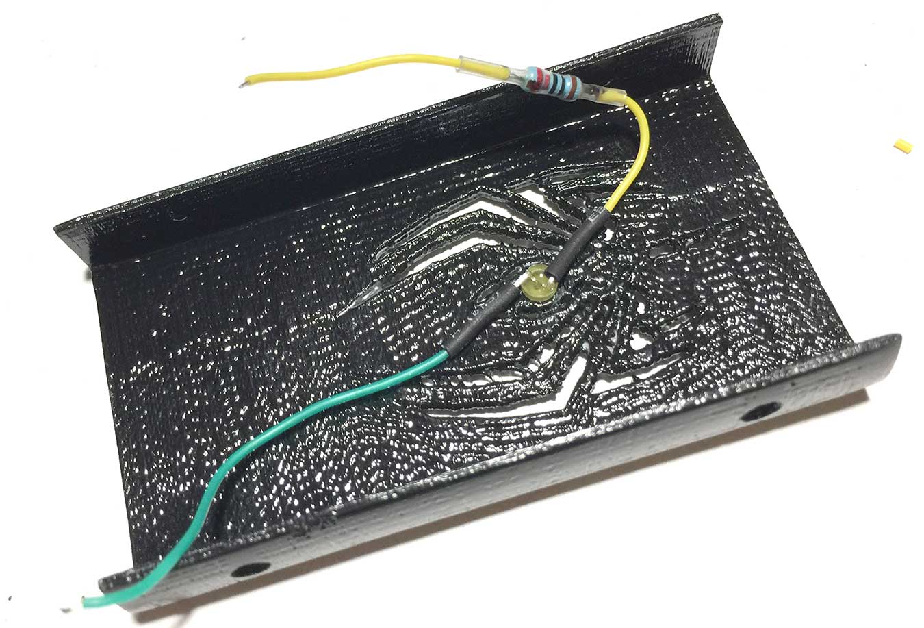
Glue Yellow LED to cover. Solder 220Ohm resistor to +:
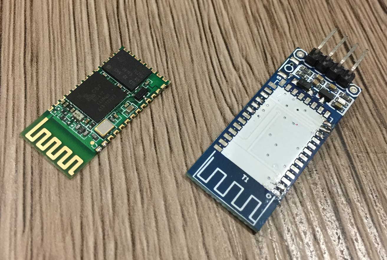
Prepare bluetooth module. We need naked HC-06 module:
We need separate bluetooth module because internal ESP32 BLE/bluetooth support can not ensure reliable simultaneous Wifi and Bluetooth communication.
Prepare DC-DC module. Set output voltage to 5V before soldering everything together.
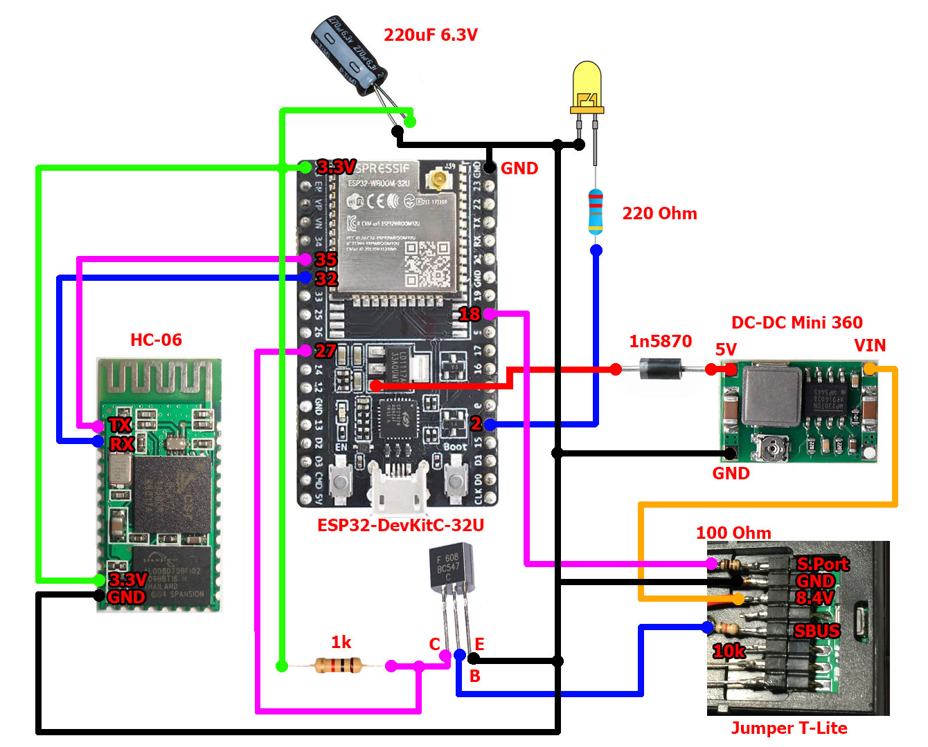
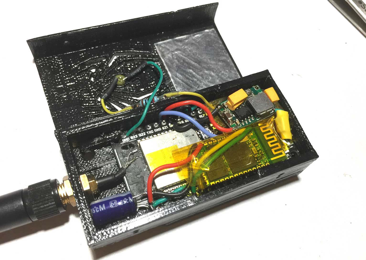
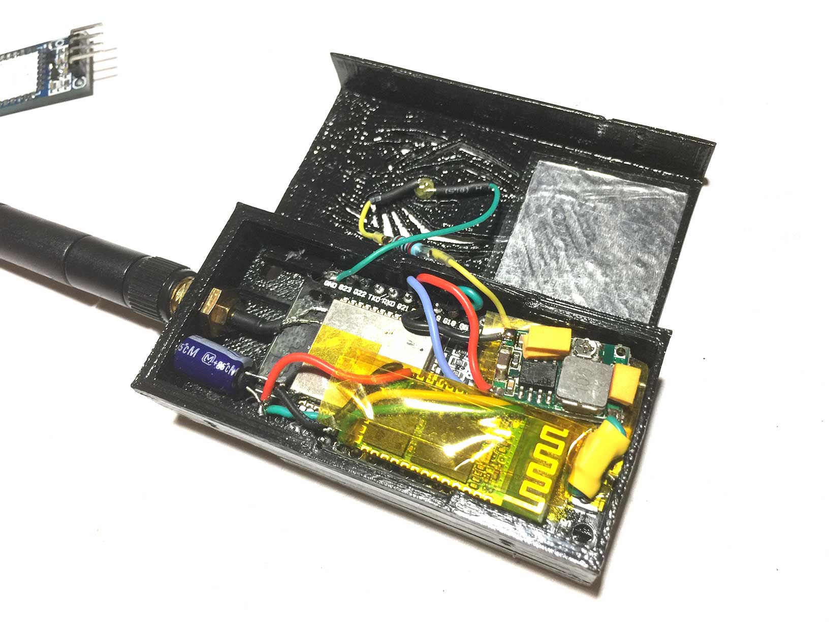
Solder everything together according to connections diagram. Use capton type to isolate parts.
Note that DC-DC output is connected through diode to LDO regulator input on ESP32 board, not to 5V pin, because 5V pin is directly connected to USB +5V rail. We need to pass voltage to LDO AFTER diode on ESP32 board. Otherwise DC-DC would output voltage to USB connector.
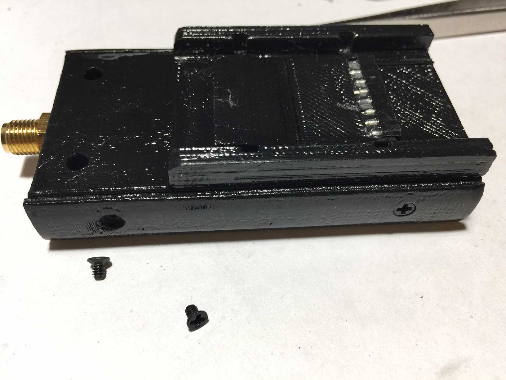
Double-check all connections. Use M2.5 bolts to fix cover on the main part:
Flash module with Examples/tx_external_module/
Upload filesystem Examples/tx_external_module/ (on the left side of the screen in PlatformIO IDE, select PlatformIO -> Upload filesystem image)
Configure T-Lite to output SBUS (normal SBUS => inverted uart).
Module can work in multiple modes. Mode is configured in profile. Profile is selected depending on CH16 value from RC Controller. Configure CH16 mixer to output constant value in OpenTX (use MAX with Weight 0 and adjust Offset).
There are 10 profiles. Profile 10 is reserved for Configuration mode.
For example:
- 1000...1100 ( or -100%) - profile 1
- 1100...1200 ( or -80%) - profile 2
- 1200...1300 ( or -60%) - profile 3
- 1300...1400 ( or -40%) - profile 4
- 1400...1500 ( or -20%) - profile 5
- 1500...1600 ( or 0%) - profile 6
- 1600...1700 ( or +20%) - profile 7
- 1700...1800 ( or +40%) - profile 8
- 1800...1900 ( or +60%) - profile 9
- 1900...2000 ( or +80%) - profile 10 (Configuration mode)
See profiles https://github.com/RomanLut/hx_espnow_rc/blob/main/doc/tx_profiles.md
